Maintenance
50940411/G0219 158 Printed in U.S.A.
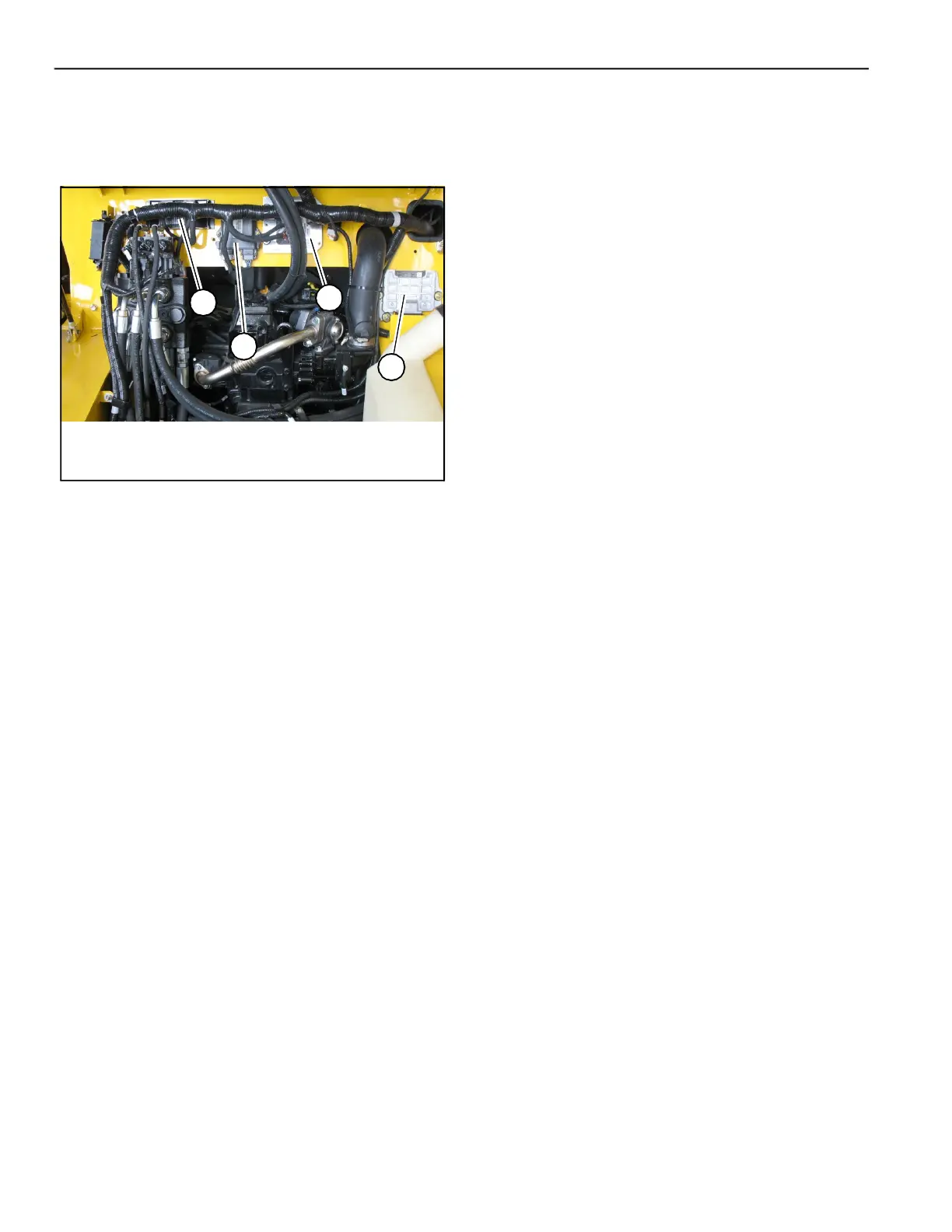
Control Modules
Electrical control modules are located on the chassis
under the ROPS/FOPS.
Multi-function Control Module
Multi-function control module (N, Fig. 175)
provides the following control functions:
• Horn
• Fuel sender input
• Starter and parking brake interlock logic
• Hydraulic and air filters indicator inputs
• Two-speed travel logic
• Safety logic control
• Lift arm float and Hydraglide™ logic
Lift Arm and Standard Auxiliary Flow Control
Module
Control module (P) includes outputs for lift arm and
standard auxiliary hydraulics flow function.
Engine Control Module (ECU)
Control module (Q) controls engine control logic
and error reporting.
Main/Drive Control Module
Main/drive control module (R) provides the
following control functions
• Logic for travel drive and main control valve
• Bucket function
• Transmission, control valve and controller com-
munication error codes broadcast output
Fig. 175 – Control Modules (Models RT175/RT210
Shown; RT250 Similar)
N
P
Q
R
 Loading...