Schematics
50940411/G0219 234 Printed in U.S.A.
Model RT175 with interim Tier 4 Engines
(Serial Numbers 10951 - 811000)
Model RT210 with interim Tier 4 Engines
(Serial Numbers 21201 - 921000)
RT175 (Serial Numbers 10951 - 811000), RT210 (Serial Numbers 21201 - 921000)
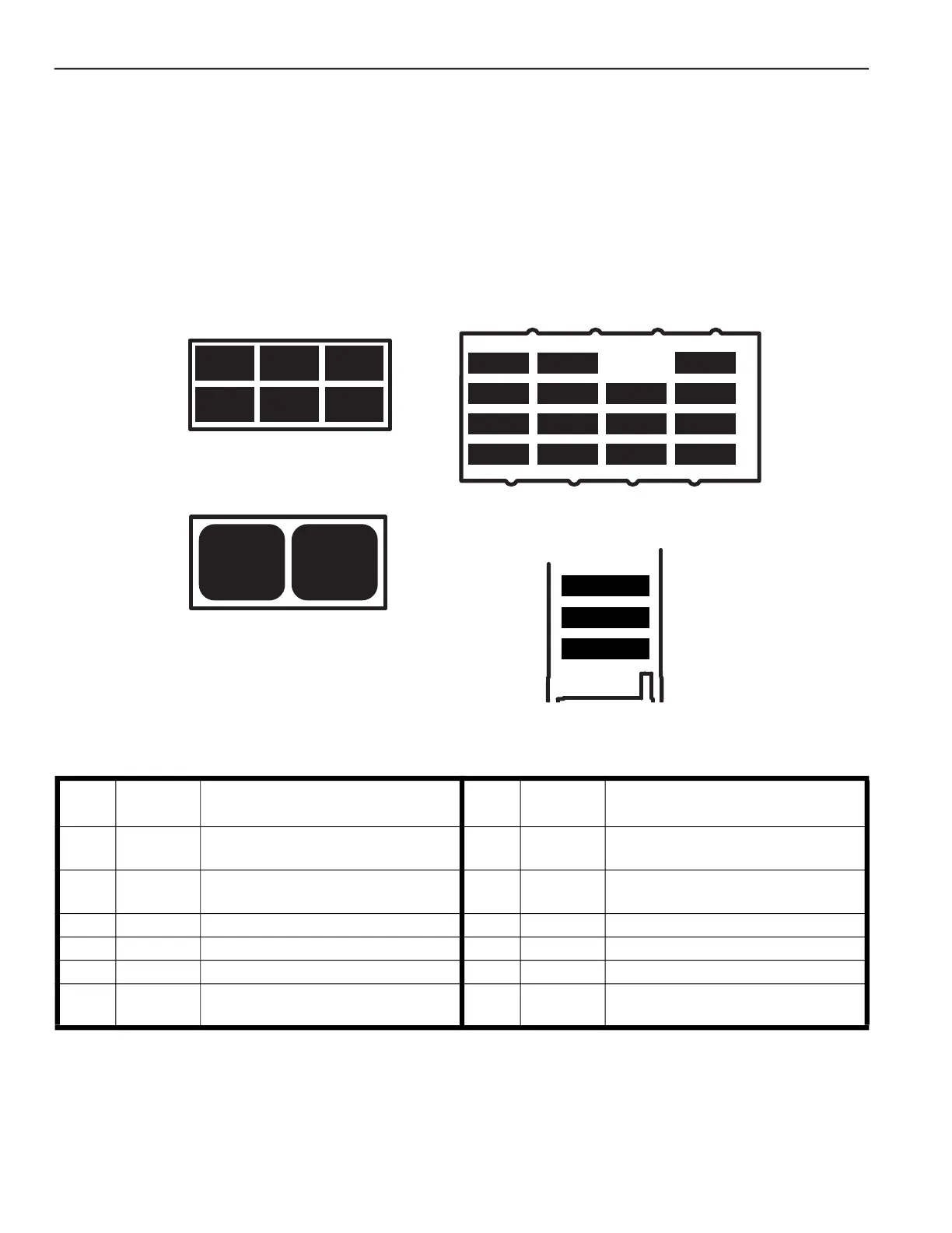
Fuse/Relay Locations Index
R4
Start
Relay
R5
HVAC
Relay
C135 – RELAY BLOCK
C51 – FUSE BLOCK
R10 R8 R6
R11 R9 R7
C134 – RELAY BLOCK
MAXI 3 – 40A
MAXI 2 – 80A
MAXI 1 – 60A
C133 – FUSE BLOCK
F13-15A
F14-5A
F15-10A
F11-20A
F6-15A
F7-10A
F8-20A
F1-10A
F2-10A
F3-20A
F4-10A
F9-20A
F10-10A
120Ω120Ω
Fig. 181 – RT175 / RT210 with interim Tier 4 Engines Relay/
Fuse Box Decals Detail
Table 66: RT175 / RT210 with interim Tier 4 Engines - Relays
Relay
Schematic
Page
Circuit / Notes Relay
Schematic
Page
Circuit / Notes
R1 238
Power / Relay not in fuse box; refer to
page 157
R2 238
Starter Solenoid / Relay not in fuse box;
page 157
R3 240
Main / Relay not in fuse box; refer to
page 157
R4 242 Start
R5 247 HVAC R6 240 Rack Actuator
R7 247 AC Condenser Fan R8 248 Work Lights
R9 243 Maestro 2 Power R10 249 Wiper Motors
R11 242 Park Brake Switch R12 238
Engine Pre-Heat / Relay not in fuse box;
refer to page 156
 Loading...