Operation
Printed in U.S.A. 105 50940411/G0219
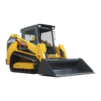
7. Make sure the locking pins (F, Fig. 103) are
fully engaged down through the holes in the
attachment.
To prevent unexpected release of the
attachment from the hitch, be sure to properly
secure the hitch latch pins by hitch lock lever
(G, Fig. 102) all the way to the left (manual All-
Tach® hitch) or by ensuring that the safety flags
(H, Fig. 102) are all the way to the outside
(Power-A-Tach® hitch).
Locking pins (F) must be fully engaged through
the holes in the attachment frame before using
the attachment. The attachment could fall off if it
is not locked on the hitch and cause serious
injury or death.
Disconnecting Attachments
Position the attachment so that after
disconnecting the attachment will stand safely
and not tip over. Serious injury can occur if an
attachment tips over onto a person.
1. Empty the attachment and drive to a open, level
area to disconnect the attachment.
2. Lower the attachment to the ground.
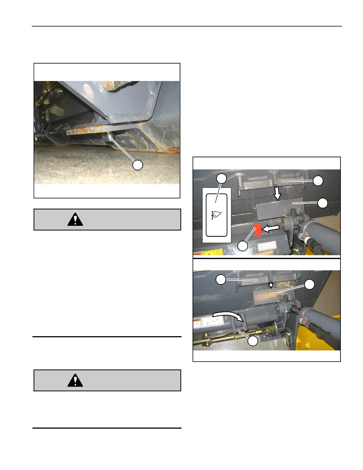
3. Place the attachment lock into the unlocked
position (Fig. 104):
• Power-A-Tach® system hitch – Press the bot-
tom of hitch lock switch (I) until safety flags
(H) have moved all the way in.
• Manual attachment hitch – Perform the
“Mandatory Safety Shutdown Procedure” on
page 20 and move hitch lock lever all the way
to the right (G).
4. Lower the lift arm until tabs (J) on top of the
attachment plate disengage out of hooks (K) on
the back of the attachment.
5. Look behind you for bystanders and obstacles.
Drive straight back in reverse away from the
attachment.
Fig. 103 – Attachment Locking Pins
F
Manual Attachment Hitch Shown, Power-A-Tach®
Quick Attach System Hitch Similar
Fig. 104 – Attachment Hitch – Unlocked
I
H
K
J
Manual Attachment Hitch Disconnection
Power-A-Tach® Quick Attach System Hitch Disconnection
K
J
G
 Loading...