COMMISSIONING
126 Service Manual Part No.: 4417340 Revision 1
954 SmartServo FlexLine
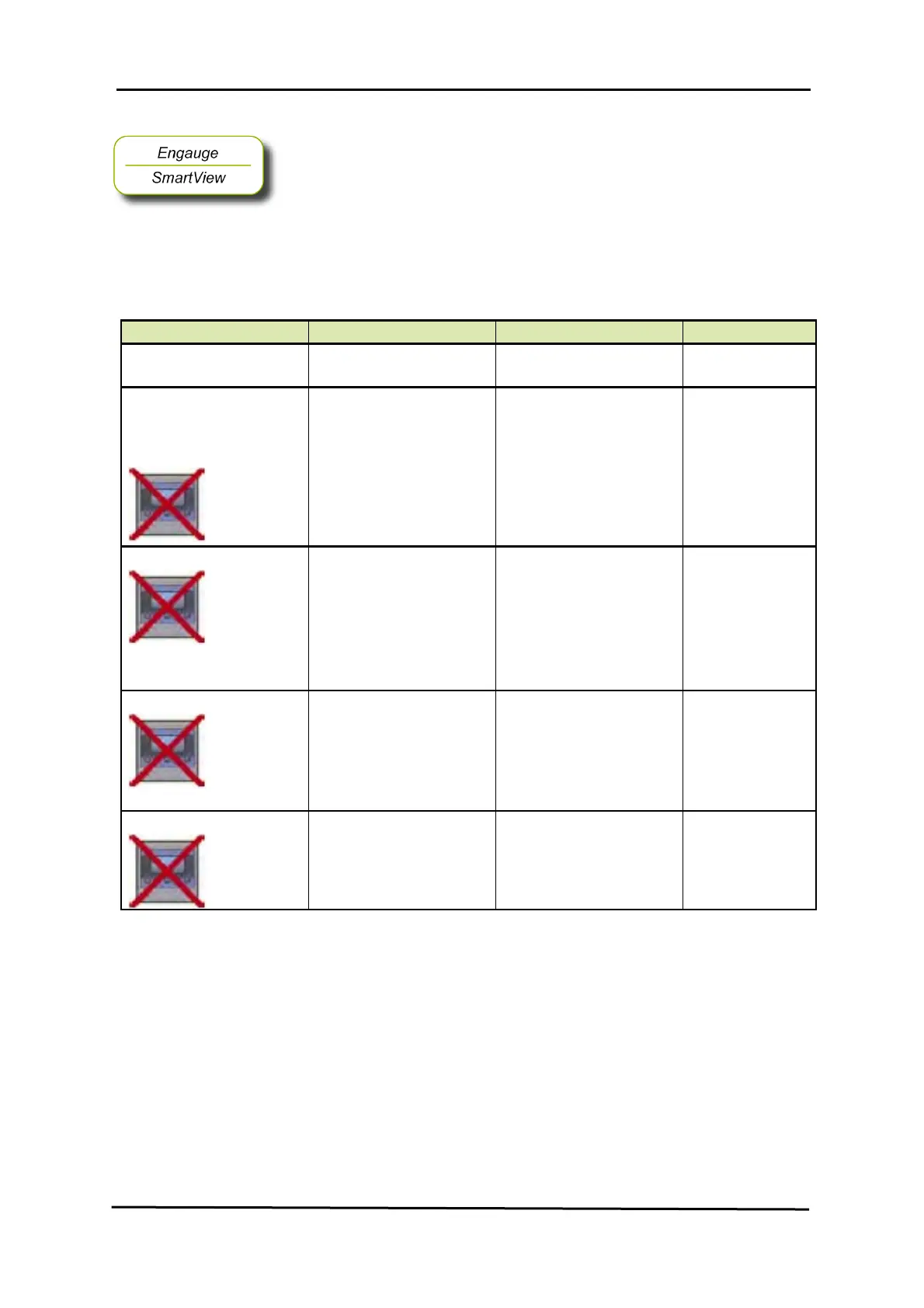
☛ The following entities can be set by Engauge or HART
SmartView for a
correct functioning of the FII-VT module in an instrument.
Name Explanation Value Range Default
[Water probe length]
The length of a water probe
floating point number:
<-x.x .. +x.x>
<0.5>
[High High alarm]
[High Alarm]
[Low Alarm]
[Low Low alarm]
4 thresholds for activating a
related alarm status in the
Primary Value
floating point numbers:
<-x.x .. +x.x>
<+1.0E22>
[Alarm test enable]
Enables (if activated, see
next listed entity) the
simulation of one of the 4
alarms for a minute, by
simulating the actual
measured Primary Value is
below or above the alarm
threshold.
<enable>
<disable>
<disable>
[Alarm test]
Activates and selects at the
same time the Alarm test (if
enabled with the [Alarm test
enable] listed before, and th
4 alarm thresholds are
properly set).
[No Alarm]
[High High alarm] [High
Alarm]
[Low Alarm]
[Low Low alarm]
<No Alarm>
[Function identification]
The current module’s
function name. This function
is visible on the HART
SmartView display.
13 characters
<Water level>

 Loading...


