SYSTEM ARCHITECTURE
26 Service Manual Part No.: 4417340 Revision 1
954 SmartServo FlexLine
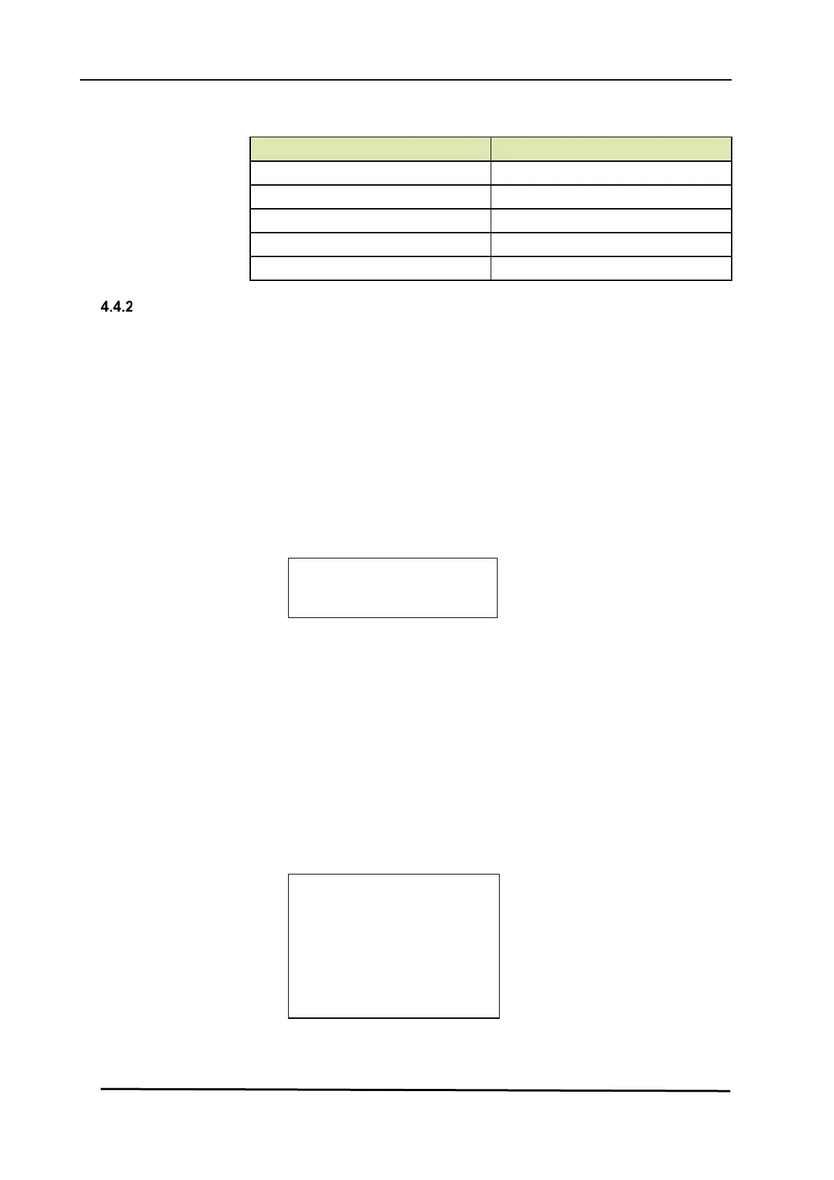
Status Category Display Text
over range over range
under range under range
no data available no data
un-initialized no init
killed killed
Status Entities on
HART SmartView
Select sub-menu “commissioning” from the main menu to view the
survey results of all FlexConn modules present in the 954 SmartServo
FlexLine system.
Each module is followed by an indication for the “Health” and the
“Commissioned” status respectively. In case of an unreliable or fault
situation, the “Information” column displays an information code in
addition. This information code reveals the specific reason about the
current status.
This diagnostic is available for each individual FlexConn module. See
example below.
H C
I
FII-DO G N
The “Health” indication is as follows:
“G” = Good
“U” = Uncertain
“B” = Bad
The “Commissioned” indication is as follows:
“Y” = the most important entities are set correctly
“N” = the most important entities are not set correctly
Starting from the “commissioned” menu and selecting the specific
FlexConn module, the above diagnostics is repeated for each
module function. See example below.
FII-DO:>
board H C I
Relay 1 G N
Relay 2 G Y
Relay 3 U Y nnn
Relay 4 B Y

 Loading...


