COMMISSIONING
130 Service Manual Part No.: 4417340 Revision 1
954 SmartServo FlexLine
• MRT (see Figure 7-20)
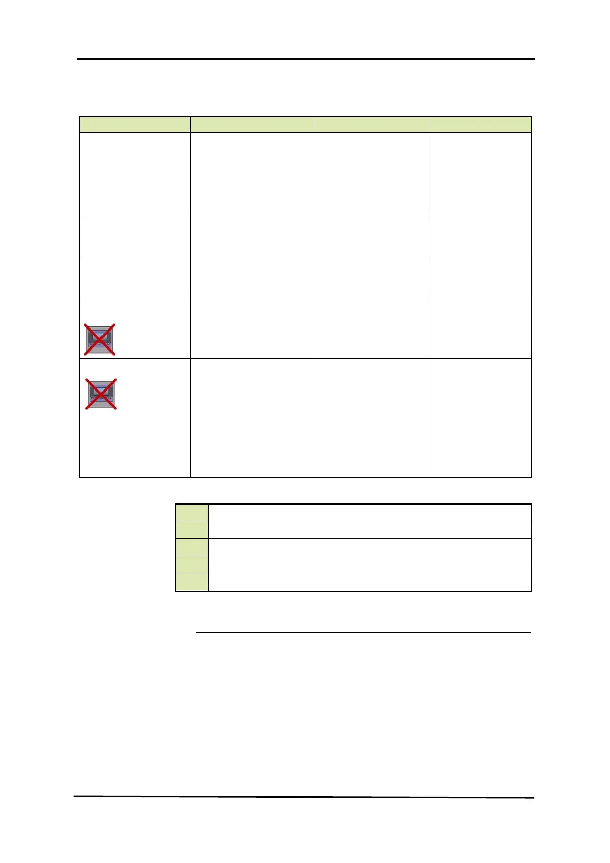
Name Explanation Value Range Default
[Element type]
See TABLE below.
3 characters
<RCB>
<RCN>
<RCS>
<QCB>
<QCN>
<QCS>
<--->
[Number of elements]
The number of elements
(resistors) an MRT probe
has
<1 .. 14> <0>
[Lowest element offset]
The distance from tank zero
till the lowest position of the
MRT probe
floating point number:
<-x.x .. +x.x>
<80.0>
[MRT element length] if MRT
length table = <T>
The lengths of the MRTs
including anchor eye
14 floating point numbers:
<-x.x .. +x.x>
<0,0,0,0,0,0,0,0,0,0,0,0,0,0>
[MRT length table]
Specifies whether a fixed
range of MRT resistors is
used (= <F>) or user-
configured lengths (= <T>).
Fixed lengths are:
0.25 / 0.65 / 1.25 / 1.95 /
2.85 / 4.15 / 5.65 / 7.35 /
9.25 / 11.65 / 14.65 /
18.45 / 22.95 / 29.65
1 character
<F>
<T>
<F>
R..
= an MRT without spot element
Q..
= an MRT with spot element
.CB
Rth = 90.2935 + T x 0.38826 (- 100 through + 280 °C)
.CN
Rth = 90.4778 + T x 0.38090 (- 100 through + 280 °C)
.CS
Rth = 90.5000 + T x 0.38730 (- 100 through + 280 °C)
Table 7-7 Element type definitions

 Loading...


