
 Loading...
Do you have a question about the Honeywell FlexLine SmartServo 954 and is the answer not in the manual?
| Brand | Honeywell |
|---|---|
| Model | FlexLine SmartServo 954 |
| Category | Measuring Instruments |
| Language | English |
Emphasizes personal safety and critical warnings for instrument handling.
Addresses safety in hazardous/safe areas and required technician qualifications.
Outlines procedures for commissioning and maintenance, including installation and grounding.
Explains the basic principle of servo-based measurement using a displacer and force transducer.
Provides an overview of servo gauges, their evolution, and advantages over float gauges.
Describes the system built from interchangeable hardware modules and FlexConn architecture.
Explains the flexibility and functionality of FlexConn modules as building blocks of the system.
Details the HART SmartView tool for setting and controlling module settings.
Describes the Engauge service tool for computer application settings and module configuration.
Introduces HART SmartView as the basic tool for communication and control.
Describes the Engauge service tool for computer application settings and module configuration.
Outlines preliminary steps and references the Installation Manual for the 954 SmartServo FlexLine.
Lists essential checks for mechanical and electrical installation before starting commissioning.
Provides an overview of commissioning information for FlexConn modules and text conventions.
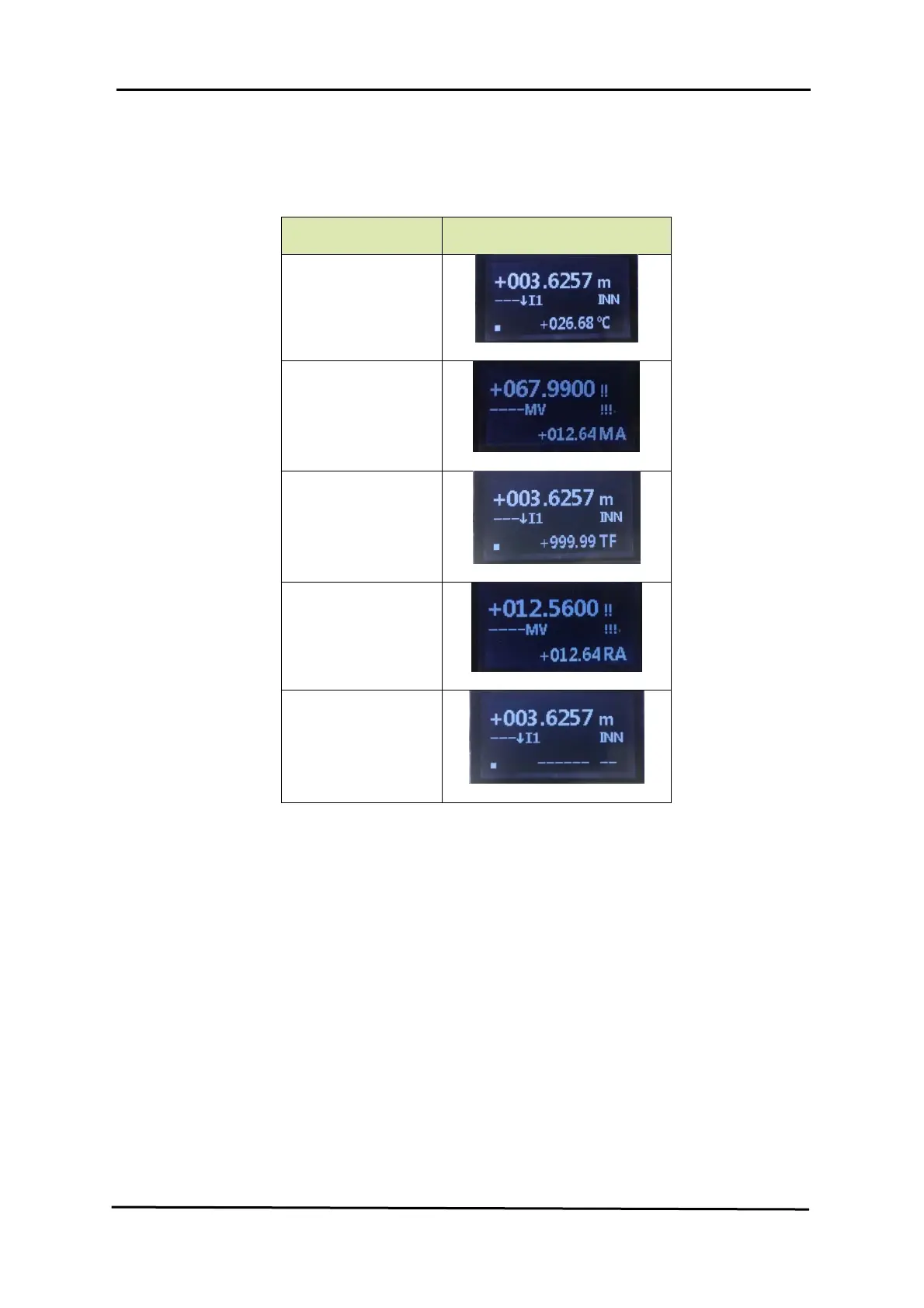
Details the commissioning and display screen configurations for the TII-LCD module.
Introduces the FII-SIL board for overfill and underfill protection, certified for Safety Instrumented Systems.
Details error codes, possible reasons, resolutions, and safety function status definitions.
Covers commissioning requirements and periodic proof testing procedures for the FII-SIL module.
Details the Servo Auto Test (SAT) function for reducing overfill/underfill risk and its manual execution.
Outlines available tests for checking maintenance needs like bearing quality and displacer weight.


