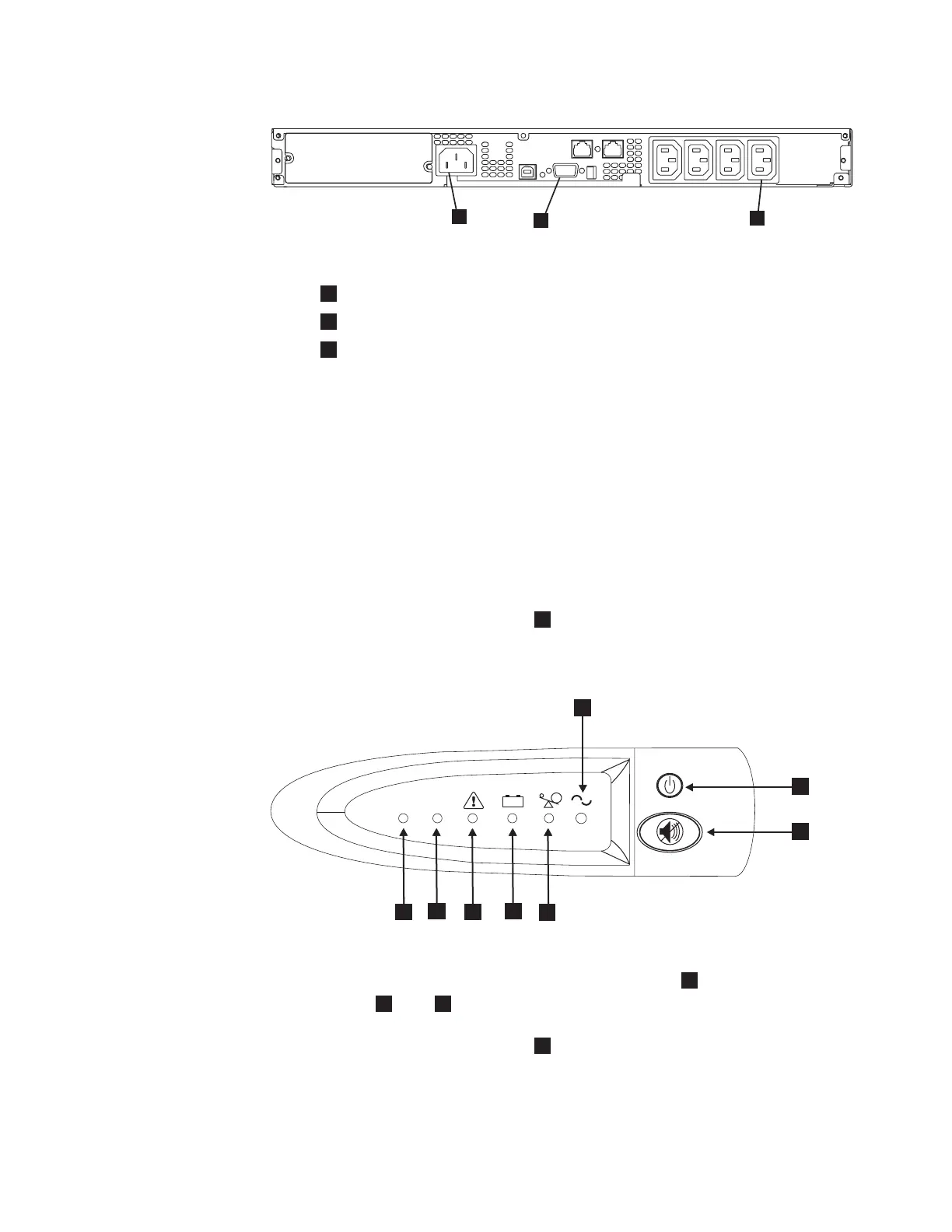
1
Mains power connector
2
Communication port
3
Load segment 2 receptacle
Attention: Ensure that you comply with the following requirements:
v The voltage supplied to the 2145 UPS-1U must be 200 – 240 V single phase.
v The frequency supplied must be 50 or 60 Hz.
Notes:
a. The 2145 UPS-1U has an integrated circuit breaker and does not
require external protection.
b. The 2145 UPS-1U is intended to maintain power on SAN Volume
Controller nodes until data can be saved to the local hard disk drive.
Only SAN Volume Controller nodes can be plugged into the 2145
UPS-1U or the SAN Volume Controller cluster malfunctions.
8.
Press and hold the on/off button
2
for approximately five seconds. The front
panel indicators cycle through a startup sequence while the 2145 UPS-1U
conducts a self-test.
When the self-test is complete, the power-on indicator
1
and the load
indicators (
7
and
8
) illuminate to indicate that power is being supplied by
the 2145 UPS-1U. The 2145 UPS-1U is now in normal mode, and is charging its
battery. If the power-on indicator
1
is flashing red and the alarm is sounding,
the voltage range setting might not be correct. When a SAN Volume Controller
is connected to the 2145 UPS-1U, the SAN Volume Controller automatically
adjusts the voltage range setting. Take no action for this alarm condition unless
1yz09b
1
2
3
Figure 56. 2145 UPS-1U (rear view)
+ -
LOAD 1LOAD 2
1yyzvm
5
6
7
8
1
2
3
4
Figure 57. The 2145 UPS-1U front panel assembly
Appendix A. SAN Volume Controller 2145-8F4 and SAN Volume Controller 2145-8F2 85
 Loading...


