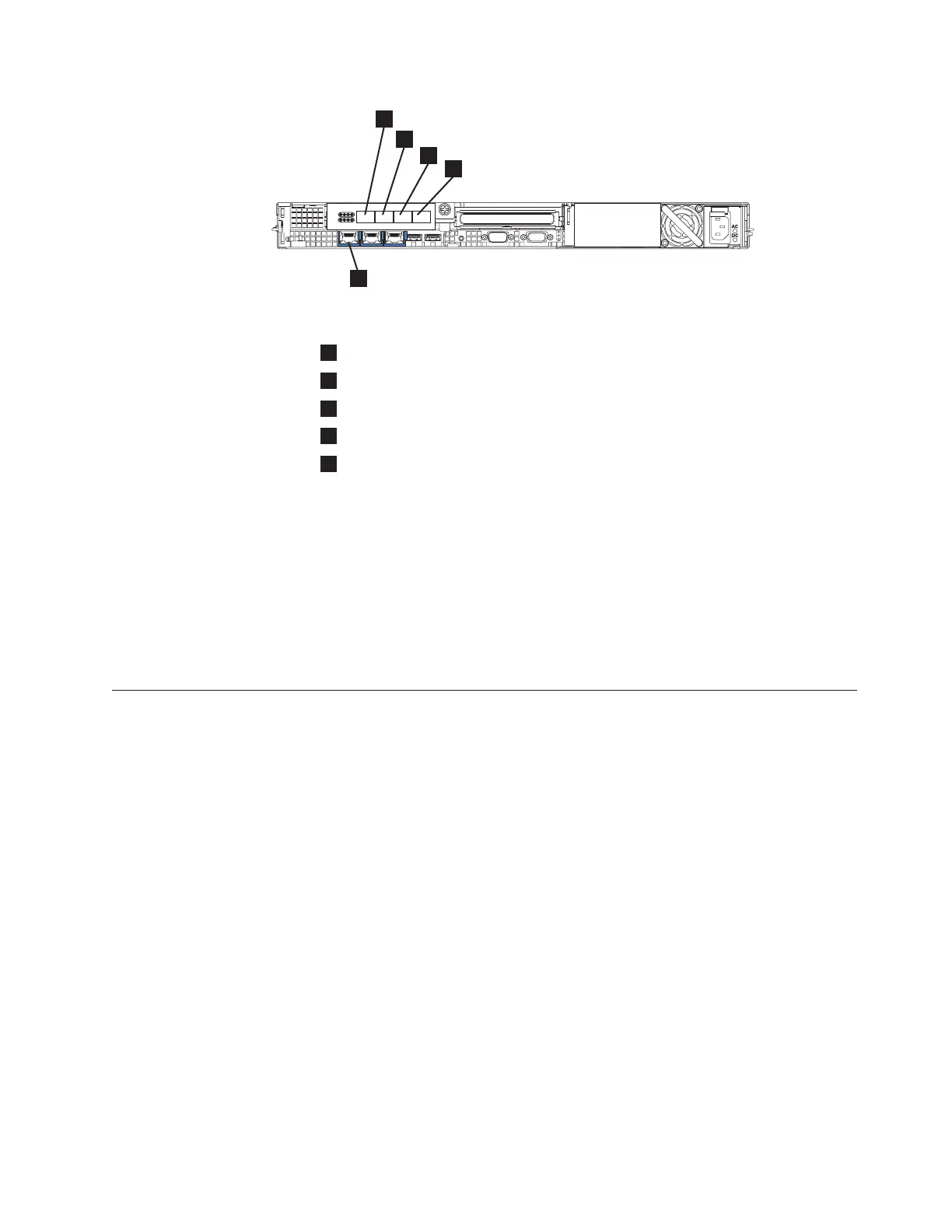
1
Fibre-channel port 1
2
Fibre-channel port 2
3
Fibre-channel port 3
4
Fibre-channel port 4
5
Ethernet port 1
Attention: When routing the fibre-channel cables, do not tighten the cable
straps or bend the cables to a radius smaller than 76 mm (3 in.).
3. Connect the fibre-channel cables to the fibre-channel ports as required by the
user’s configuration.
4. Connect the other ends of the fibre-channel cables to the proper connectors of
the fibre-channel switches.
Complete steps 1 on page 58 through 4 for each node that you need to connect to
the SAN and to the Ethernet network.
Verifying the SAN Volume Controller 2145-8G4 installation
You must verify the SAN Volume Controller installation after the installation has
completed.
This task shows you how to verify the installation after you install the SAN
Volume Controller in the rack and connect it to the uninterruptible power supply,
the storage area network (SAN), and the Ethernet.
Note: If at any point the SAN Volume Controller does not operate as described,
see “MAP 5000: Start” in the IBM System Storage SAN Volume Controller:
Service Guide, unless a different maintenance analysis procedure (MAP) is
specified.
Perform the following steps to verify installation:
1. Press the SAN Volume Controller power switch. Verify that the green power
light is on. If the light is not on, see “MAP 5000: Start” in the IBM System
Storage SAN Volume Controller: Service Guide to repair the problem.
Note: You do not need to install any software. The node boots automatically.
Verify that the node is booting without error. If it boots without error, either
the Charging message or Cluster: is displayed in the first line of the
front-panel display.
svc00228
1
2
3
4
5
Figure 35. Connectors at the back of the SAN Volume Controller 2145-8G4
Chapter 6. Installing the SAN Volume Controller 2145-8G4 hardware 59
|
|
|
 Loading...


