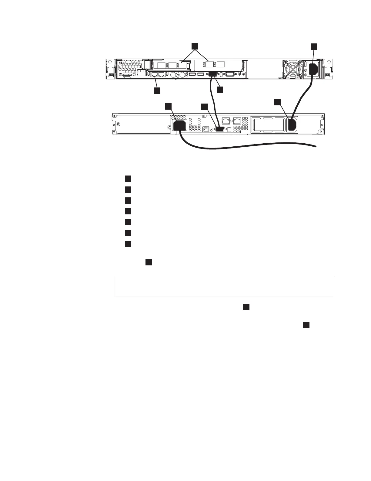
1
Fibre-channel ports
2
Power connector
3
Serial connector
4
Ethernet ports
5
Main power connector
6
Communication port
7
Load segment 2 receptacle
2. Place the other end of the power cable into the rightmost load segment 2
receptacle
7
on the 2145 UPS-1U.
DANGER
You
have already switched on the 2145 UPS-1U. The output sockets of the
2145 UPS-1U are live.
3. Plug the signal cable into the serial connector
3
located on the SAN Volume
Controller 2145-8F4 or the SAN Volume Controller 2145-8F2.
4. Place the other end of the signal cable into the communication port
6
on the
2145 UPS-1U.
The SAN Volume Controller power is now connected to the 2145 UPS-1U.
Installing the SAN Volume Controller 2145-8F4 cable retention
bracket
The cable retention bracket ensures that the SAN Volume Controller 2145-8F4 node
does not mistakenly become unplugged from the uninterruptible power supply
(UPS).
Install the SAN Volume Controller 2145-8F4 cable retention bracket after you install
the node in the rack.
To attach the bracket to the support rail, perform the following steps:
1. Install the power cable into the power supply.
svc00083
1
2
3
4
5
6
ATTENTION
CONNECT ONLY IBM SAN VOLUME
CONTROLLERS TO THESE OUTLETS.
SEE SAN VOLUME CONTROLLER
INSTALLATION GUIDE.
7
Figure 65. Connecting the SAN Volume Controller 2145-8F2 power cable to the 2145
UPS-1U
Appendix A. SAN Volume Controller 2145-8F4 and SAN Volume Controller 2145-8F2 93
 Loading...


