6. Reinstall the front panel. You might need to move the sliding section on the
front of the 2145 UPS-1U to the closed position first.
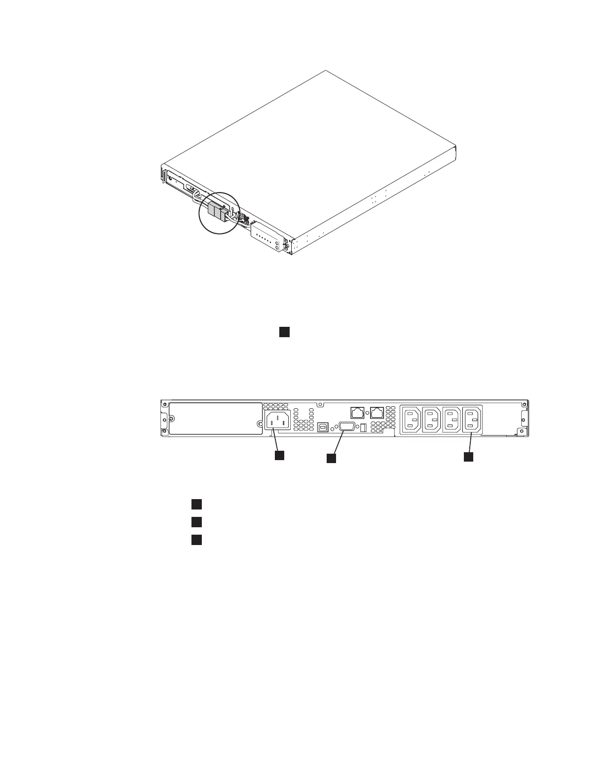
7. At the back of the 2145 UPS-1U, plug the 2145 UPS-1U main power connector
into the power socket (
1
in the following figure). The 2145 UPS-1U is in
standby mode, so all indicators are off.
It is recommended that each 2145 UPS-1U for an I/O group is connected to a
different power source.
1
Mains power connector
2
Communication port
3
Load segment 2 receptacle
Attention: Ensure that you comply with the following requirements:
v The voltage supplied to the 2145 UPS-1U must be 200 – 240 V single phase.
v The frequency supplied must be 50 or 60 Hz.
Notes:
a. The 2145 UPS-1U has an integrated circuit breaker and does not
require external protection.
b. The 2145 UPS-1U is intended to maintain power on SAN Volume
Controller nodes until data can be saved to the local hard disk drive.
Only SAN Volume Controller nodes can be plugged into the 2145
UPS-1U or the SAN Volume Controller cluster malfunctions.
svc00061
Figure 21. The 2145 UPS-1U internal battery connector
1yz09b
1
2
3
Figure 22. 2145 UPS-1U (rear view)
46 IBM System Storage SAN Volume Controller: Hardware Installation Guide
|
|
 Loading...


