4
Power, location, and system error LEDs
5
Ac and dc LEDs
Fibre-channel LEDs on the SAN Volume Controller 2145-8G4
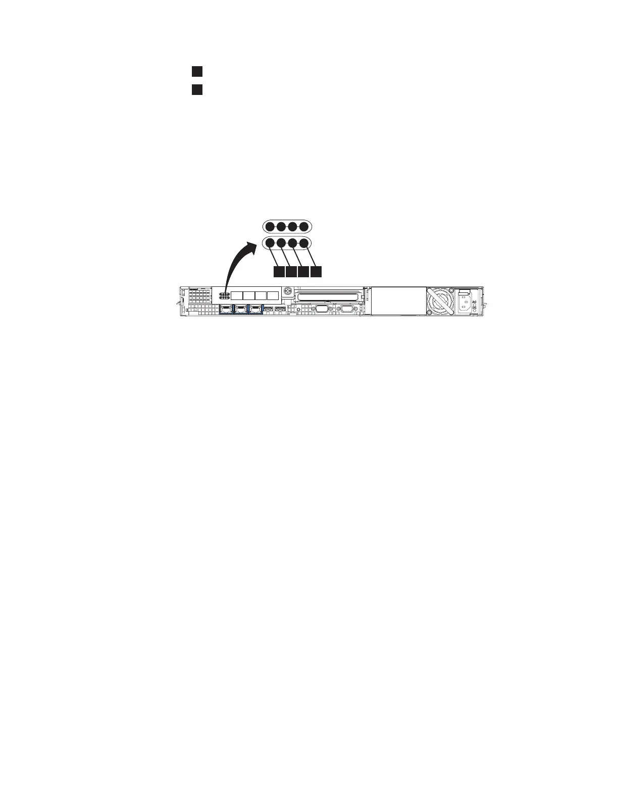
The fibre-channel LEDs on the SAN Volume Controller 2145-8G4 indicate the status
of the fibre-channel ports.
Figure 3 shows the fibre-channel LEDs on the SAN Volume Controller 2145-8G4.
.
Ethernet activity LED
The Ethernet activity LED indicates that the SAN Volume Controller 2145-8G4 is
communicating with the Ethernet network that is connected to the Ethernet port.
The Ethernet activity LED is located on each Ethernet port; Ethernet port 2 is used
only during Ethernet troubleshooting.
Ethernet link LED
The Ethernet link LED indicates that there is an active connection on the Ethernet
port.
The Ethernet link LED is located on each Ethernet port; however, only Ethernet
port 1 is used during normal operation.
Power, location, and system error LEDs
The power, location, and system error LEDs are housed together on the rear of the
SAN Volume Controller.
The following terms describe the power, location, and system error LEDs:
Power LED
This is the top of the three LEDs and indicates the following:
Off One or more of the following are true:
v No power is present at the power supply input
v The power supply has failed
v The LED has failed
On The SAN Volume Controller is powered on.
svc00218
1
3
4
2
Figure 3. SAN Volume Controller 2145-8G4 fibre-channel LEDs
Chapter 2. SAN Volume Controller overview 11
 Loading...


