Perform the following steps to attach the mounting plates to the redundant ac
power switch:
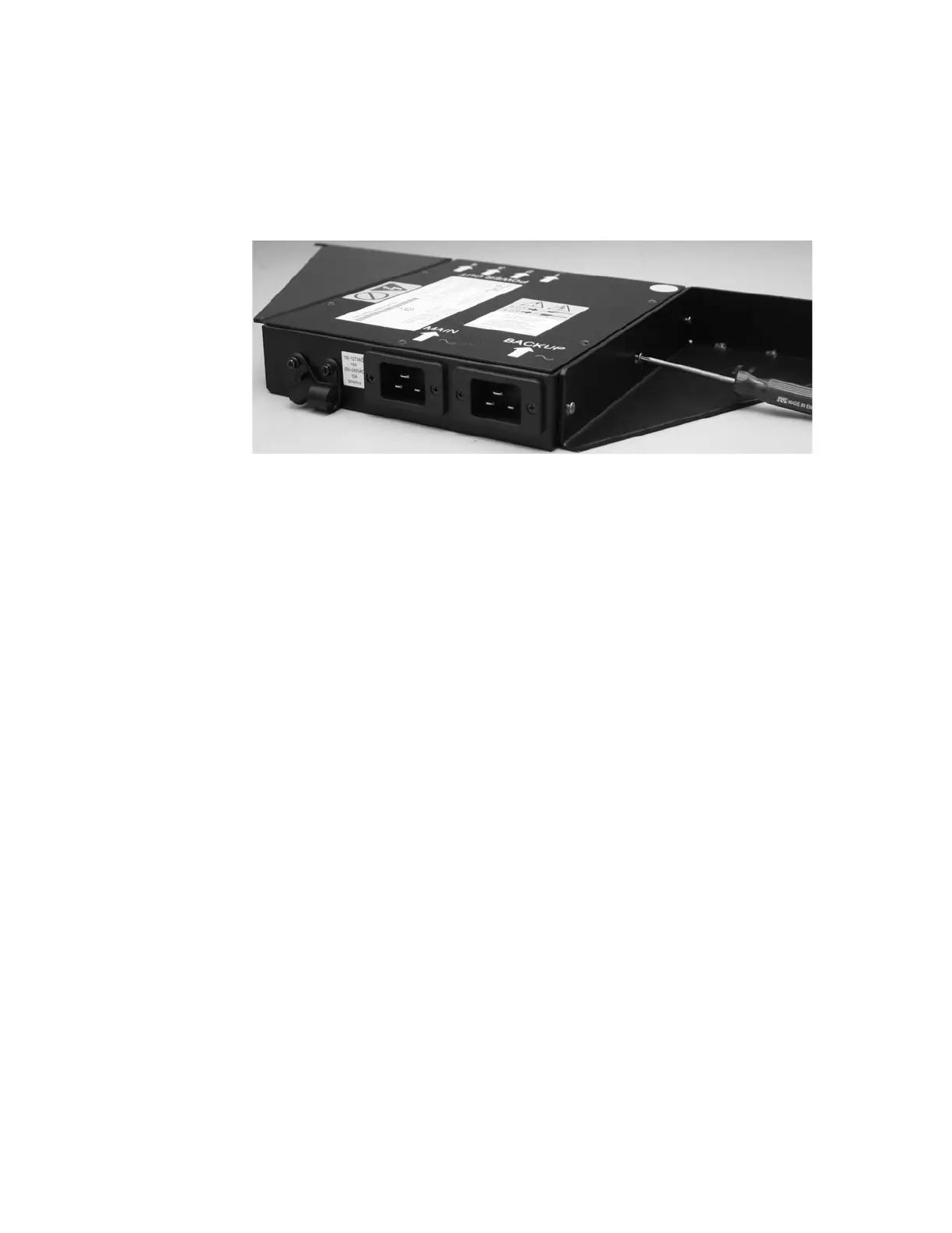
Attach each of the two mounting plates to the redundant ac power switch using
three M3 Torx T8 head screws. Position the mounting face on the side of the
redundant ac power switch containing the output power sockets. See Figure 11.
Labeling the cables
You must label each end of the two redundant ac power switch input power cables
before you connect the power input cables to the redundant ac power switch.
Perform the following steps to label each end of the two redundant ac power
switch input power cables:
1. Label the rack power distribution end “Power source <name>, outlet <id> to
redundant ac power switch <location> <MAIN | BACKUP> input”. For
example, “Power source D2, outlet 4 to redundant ac power switch pos 7
MAIN input”. One cable is labeled “MAIN”, the other is labeled “BACKUP”.
2. Label the redundant ac power switch end “redundant ac power switch
<location> <MAIN | BACKUP> input from Power source <name>, outlet
<id>”. One cable is labeled “MAIN”, the other is labeled “BACKUP”.
Connecting the power input cables to the redundant ac power
switch
You will find it easier to connect the power input cables to the redundant ac power
switch before you install the redundant ac power switch in the rack.
Perform the following steps to connect the power input cables to the redundant ac
power switch:
1. Connect the main input power cable to the redundant ac power switch.
2. Connect the backup input power cable to the redundant ac power switch.
3. Secure both the redundant ac power switch input cables using the clips of the
redundant ac power switch. See Figure 12 on page 39.
svc00294
Figure 11. Attaching the mounting plates
38 IBM System Storage SAN Volume Controller: Hardware Installation Guide
 Loading...


