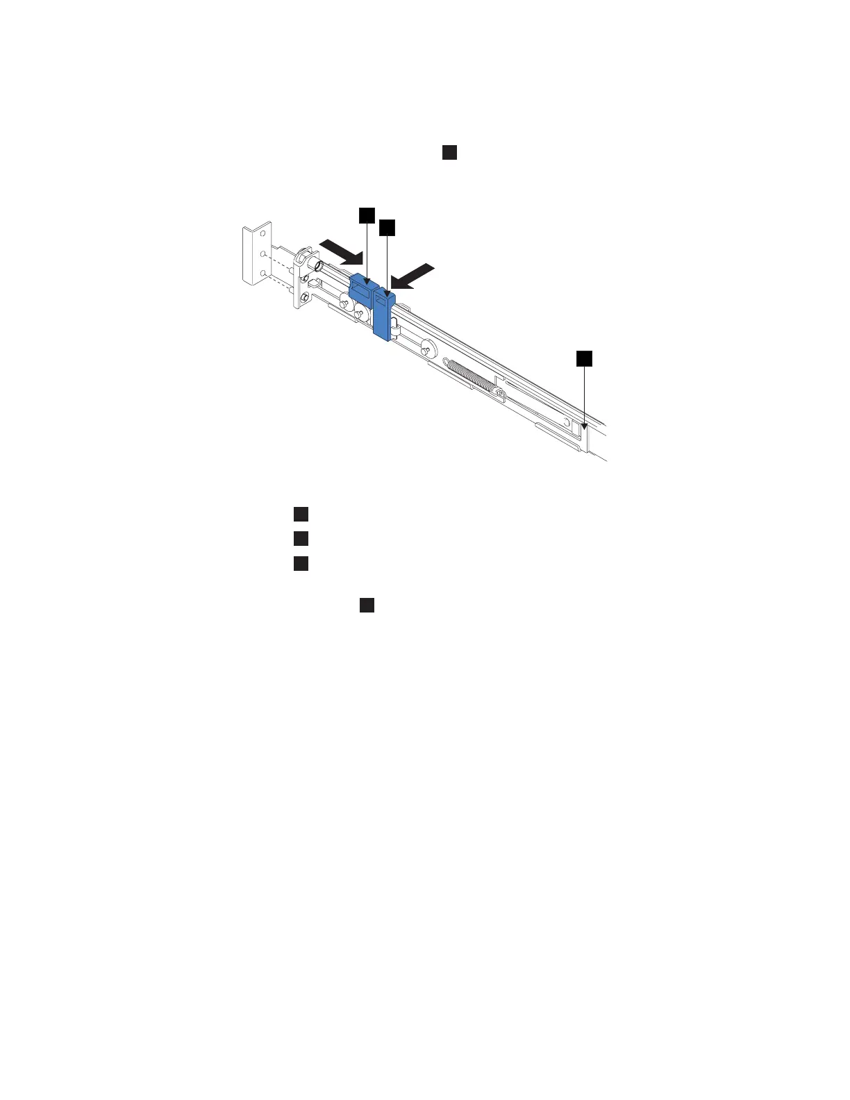
4. Continue to slide the latch-lock carrier for approximately 13 mm (0.5 in). The
latch-lever engages a hole in the back bracket assembly and holds the
latch-lock carrier in the retracted position.
5. Push the back rail bracket
1
(Figure 62) toward the front of the rail until it
stops. The rail is now at its shortest adjustment.
1
Back rail bracket
2
Latch-lock
3
Latch-lever
6. Place the front end of the left rail in the rack cabinet. Align the top of the
front bracket
1
(Figure 63 on page 90) with the required EIA marking that is
on the rack.
2
1
3
Figure 62. Opening the back latch-lock carrier assembly
Appendix A. SAN Volume Controller 2145-8F4 and SAN Volume Controller 2145-8F2 89
 Loading...


