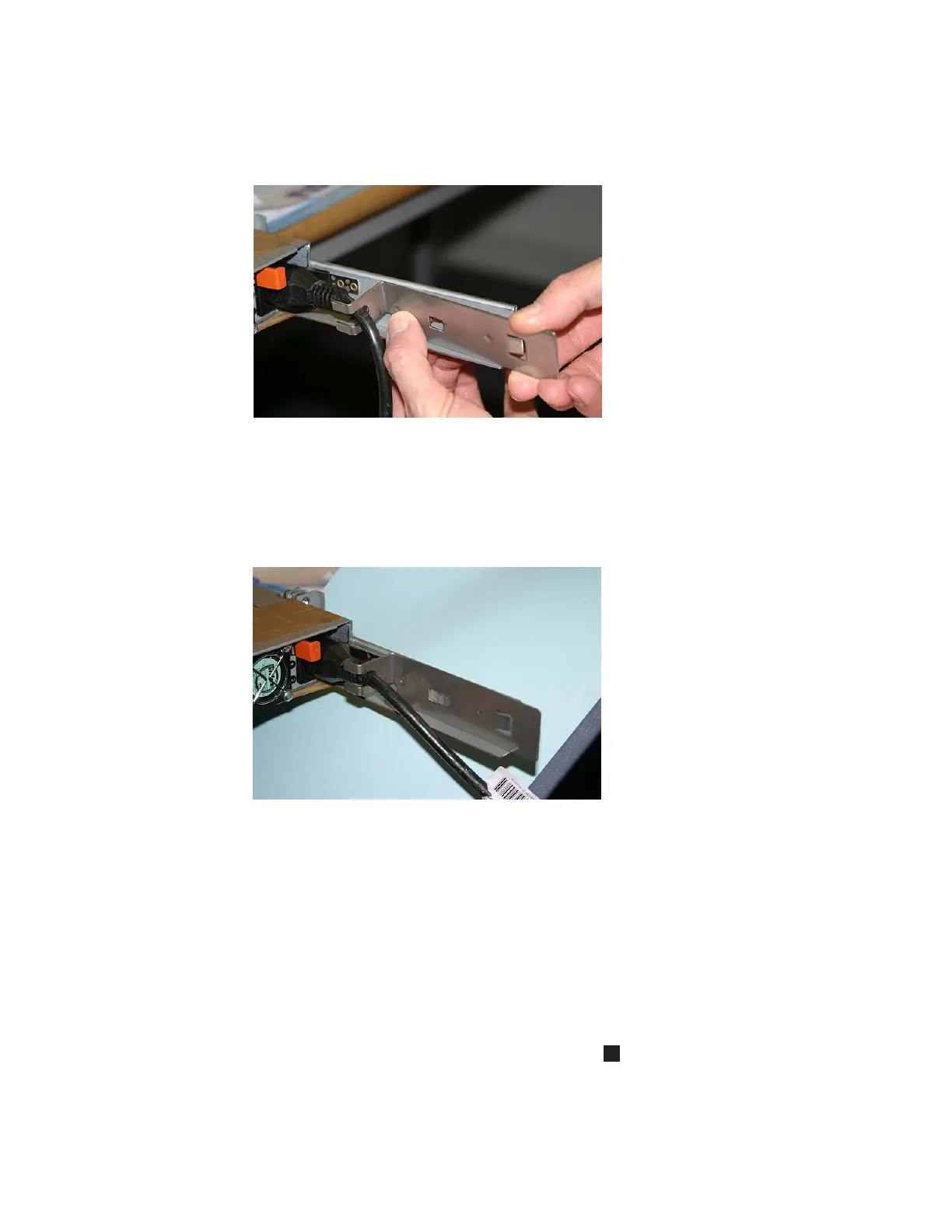
2. Insert the bracket onto the power cable so that the power cable is held by the
slot on the end of the bracket. Figure 66 provides a view of how to align the
cable retention bracket with the cable.
3. Position the cable retention bracket against the support rail and attach the
bracket onto the slot in the rear of the rail. Figure 67 provides a view of the
cable retention bracket that is attached to the SAN Volume Controller 2145-8F4.
Connecting the SAN Volume Controller 2145-8F4 or the SAN
Volume Controller 2145-8F2 to the SAN and to the Ethernet
network
Before you connect the SAN Volume Controller 2145-8F4 or the SAN Volume
Controller 2145-8F2 to the SAN, you must connect the Ethernet and fibre-channel
cables.
Before you begin this task, refer to the user’s cable connection table to find out
where to connect the Ethernet and fibre-channel cables.
1. Connect the Ethernet cable to Ethernet port 1
5
in Figure 68 on page 95 or
Figure 69 on page 95.
Attention: You must use only Ethernet port 1 on the SAN Volume Controller.
The software is configured only for Ethernet port 1.
svc00175
Figure 66. Attaching the cable retention bracket to the SAN Volume Controller 2145-8F4
power cable
svc00174
Figure 67. The SAN Volume Controller 2145-8F4 with cable retention bracket attached
94 IBM System Storage SAN Volume Controller: Hardware Installation Guide
 Loading...


