automatically adjusts the voltage range setting. Take no action for this alarm
condition unless it persists for more than five minutes after a SAN Volume
Controller 2145-4F2 has been connected to this 2145 UPS and powered on.
11. Repeat all of these steps to install additional 2145 UPSs.
Installing the SAN Volume Controller 2145-4F2
There are several steps that you must perform to install the SAN Volume
Controller 2145-4F2 node.
Installing the SAN Volume Controller 2145-4F2 consists of the following tasks:
1. Installing the support rails in the rack cabinet.
2. Installing the SAN Volume Controller 2145-4F2.
3. Connecting the SAN Volume Controller 2145-4F2 to the 2145 UPS-1U or the
2145 UPS.
Installing the support rails for the SAN Volume Controller
2145-4F2
You must install the support rails that hold the SAN Volume Controller 2145-4F2.
When you are ready to install the support rails, perform the following tasks:
v Refer to the Hardware Location Chart to determine where the SAN Volume
Controller 2145-4F2 is to be installed in the rack.
v Refer to the Electronic Industries Alliance (EIA) markings on the rack and decide
where you are going to install the support rails.
Perform
the following steps to install the support rails:
1. Check the labels on the support rails. Each rail has a label that indicates which
is the front end of the rail and whether the rail is for the left or right side of
the rack. Perform this procedure for both rails.
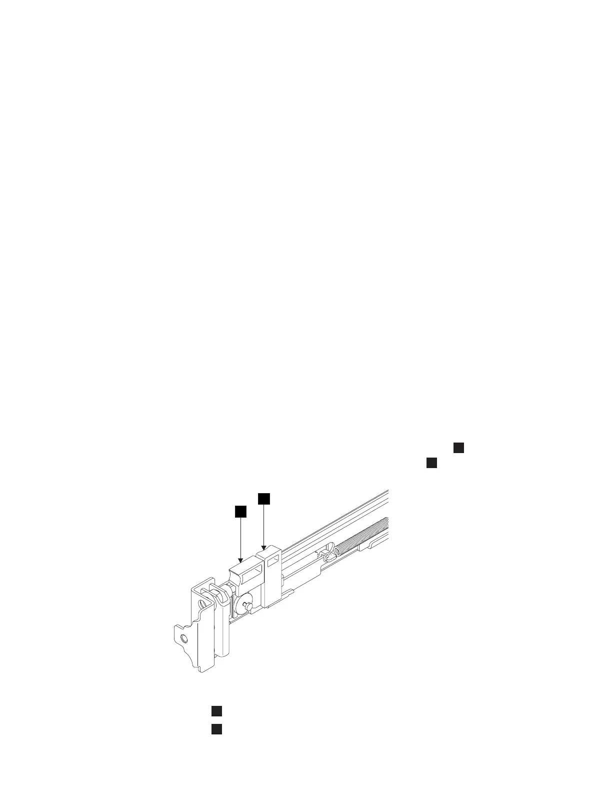
2. Put your index finger against the side of the latch-lever,
1
in Figure 91, and
put your thumb against the front of the latch-lock
2
.
1
Latch-lever
2
Latch-lock
1
2
Figure 91. Retracting the latch lock carrier
Appendix B. SAN Volume Controller 2145-4F2 129
 Loading...


