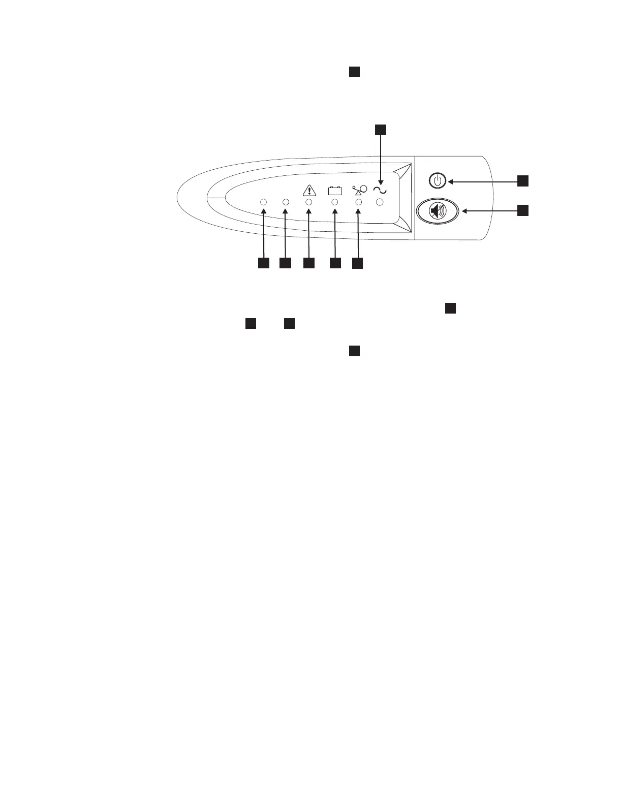
8. Press and hold the on/off button
2
for approximately five seconds. The front
panel indicators cycle through a startup sequence while the 2145 UPS-1U
conducts a self-test.
When the self-test is complete, the power-on indicator
1
and the load
indicators (
7
and
8
) illuminate to indicate that power is being supplied by
the 2145 UPS-1U. The 2145 UPS-1U is now in normal mode, and is charging its
battery. If the power-on indicator
1
is flashing red and the alarm is sounding,
the voltage range setting might not be correct. When a SAN Volume Controller
is connected to the 2145 UPS-1U, the SAN Volume Controller automatically
adjusts the voltage range setting. Take no action for this alarm condition unless
it persists for more than five minutes after a SAN Volume Controller has been
connected to this 2145 UPS-1U and powered on.
9. Repeat all of these steps to install additional 2145 UPS-1Us.
Installing the 2145 UPS-1U cable retention bracket
The 2145 UPS-1U cable retention bracket ensures that the power cable connection
between the 2145 UPS-1U and the SAN Volume Controller 2145-8G4 or the SAN
Volume Controller 2145-8F4 is stable.
Install the bracket after you have installed the power cable between the 2145
UPS-1U and the SAN Volume Controller 2145-8G4 or the SAN Volume Controller
2145-8F4 node.
You can attach the bracket by performing the following steps:
1. Install the power cable into the rightmost power supply on the rear of the 2145
UPS-1U.
2. Remove the bracket and the two screws (shown in Figure 24 on page 48) from
the packaging.
+ -
LOAD 1LOAD 2
1yyzvm
5
6
7
8
1
2
3
4
Figure 23. The 2145 UPS-1U front panel assembly
Chapter 6. Installing the SAN Volume Controller 2145-8G4 hardware 47
 Loading...


