TYPICAL PAGE - D
Two pulse hoses connect the pump to pulse fit-
tings
on
the front of the cylinder/crankcase.
• V4 Models - cylinders 1 and 3
• V6 Models - cylinders 1 and 4
Typ
ica
l
illu
s
tr
a
ti
on
for
lower
puls
e
ho
se
of
the oil sup-
V4
or
V6
Mode
ls
lift pump. A pressure-sensing
switch monitors
oil injection pressure.
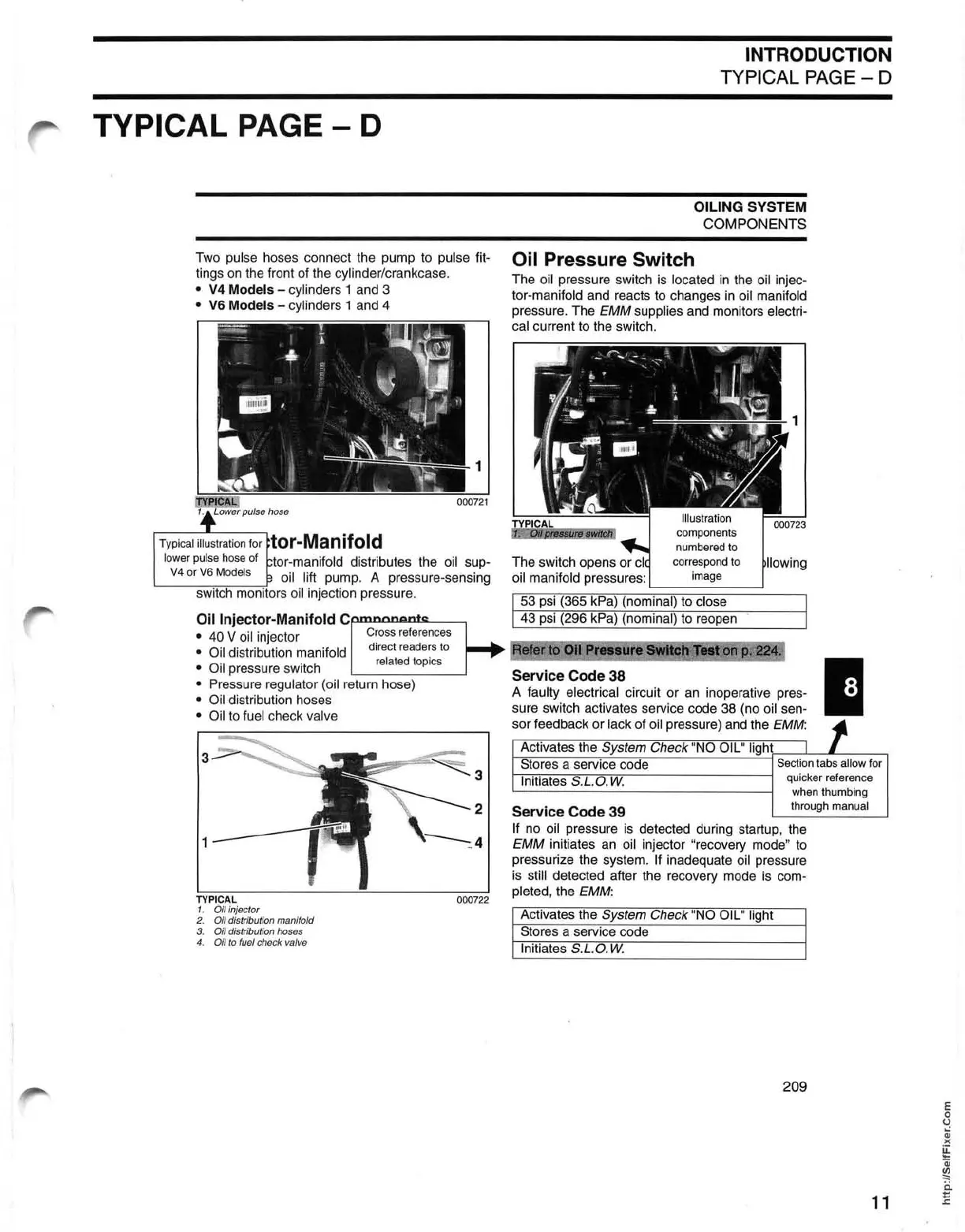
Oil Injector-Manifold
Cp.n:lnlllllQ.DlS~---,
• 40 V oil injector
Cross
r
efe
ren
ces
• Oil distribution manifold
direct
read
ers
to
related
to
pi
cs
• Oil pressure switch
• Pressure regulator (oil return hose)
• Oil distribution hoses
• Oil to fuel check valve
3
3
2
1
TYPICAL
1. Oil injector
2.
Oil distribution manifold
3.
Oil distribution hoses
4.
Oil
to
fuel check valve
INTRODUCTION
TYPICAL PAGE - D
OILING SYSTEM
COMPONENTS
Oil Pressure Switch
The oil pressure switch is located
in
the oil injec-
tor-manifold and reacts to changes
in
oil manifold
pressure. The
EMM
supplies and monitors electri-
cal
current to the switch.
components
numbered
to
The switch opens
or
correspond
to
oil manifold pressures:
image
53 psi (365 kPa) (nominal) to close
43 psi
(296 kPa) (nominal) to reopen
Service Code 38
A faulty electrical circuit or
an
inoperative pres-
sure switch activates service code
38
(no oil sen-
sor feedback
or
lack
of
oil pressure) and the EMM:
Activates the System Check "NO OIL" light
I
I
1
Stores a service code
Section
tabs
allow
for
Initiates S.L.O.
W.
quicker
reference
when
thumbing
Service Code 39
through
manua
l
If
no oil pressure
is
detected during startup, the
EMM
initiates an oil injector "recovery mode" to
pressurize the system.
If inadequate oil pressure
is
still detected after the recovery mode
is
com-
pleted, the EMM:
Activates the System Check "NO OIL" light
Stores a service code
Initiates S.L.O.
W.
209
E
o
o
W
)(
~
Qj
~
i:i
11
~
 Loading...