Power Pack Running Output
Twist and remove primary leads from ignition
coils.
Use a clockwise twist to install Stevens Number
TS-77
terminal extenders, or equivalent, to igni-
tion
coil primary posts.
Install primary leads
on
terminal extenders.
Observe proper wire routing.
Orange/blue primary
lead must
be
connected to number 1 ignition coil.
IMPORTANT: Route all tester leads so they do
not interfere with moving engine parts.
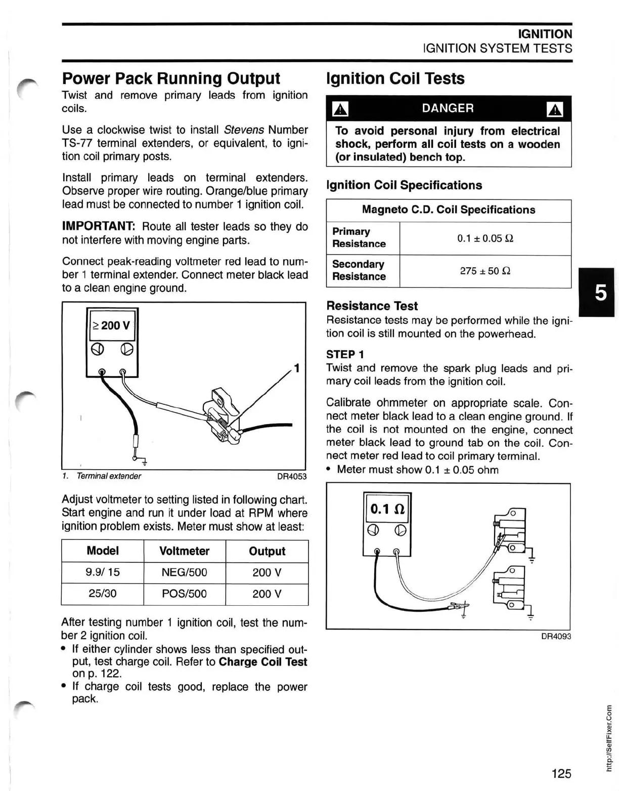
Connect peak-reading
voltmeter
red
lead to num-
ber
1 terminal extender. Connect meter black lead
to a clean engine ground.
1
1. Terminal extender
DR4053
Adjust voltmeter to setting listed
in
following chart.
Start engine and
run
it
under load at
RPM
where
ignition
problem exists. Meter must show at least:
Model
Voltmeter
Output
9.9/15
NEG/SOO
200 V
25/30
POS/SOO
200 V
After testing number 1 ignition coil, test the num-
ber
2 ignition coil.
•
If
either cylinder shows less than specified out-
put, test charge
coil. Refer to Charge Coil Test
on
p.
122.
• If charge coil tests good, replace the power
pack.
IGNITION
IGNITION
SYSTEM TESTS
Ignition Coil Tests
~
DANGER
~
To
avoid
personal
injury
from
electrical
shock,
perform
all
coil
tests
on
a
wooden
(or
insulated) bench top.
Ignition Coil Specifications
Magneto C.D. Coil Specifications
Primary
0.1
± 0.05 Q
Resistance
Secondary
275 ± 50 Q
Resistance
Resistance Test I
Resistance tests may
be
performed while the igni-
tion
coil
is
still mounted
on
the powerhead.
STEP 1
Twist and remove the spark plug leads and pri-
mary
coil leads from the ignition coil.
Calibrate
ohmmeter
on
appropriate scale. Con-
nect meter
black lead to a clean engine ground.
If
the coil
is
not mounted
on
the engine, connect
meter
black lead to ground tab
on
the coil. Con-
nect meter
red
lead to coil primary terminal.
•
Meter must show
0.1
± 0.05 ohm
DR4093
125
E
o
U
Qj
)(
~
Qj
~
ii
E
 Loading...