Assemble the following components from Univer-
sal Puller Set, PIN 378103:
• Body,
PIN
307636
• Pressing Screw, PIN 307637
• Handle,
PIN
307638
9.9/15 MODELS
• Three screws, PIN 307641
• Three washers, PIN 307639
25/30 MODELS
• Three screws,
PIN
307642
• Three washers, PIN 307640
"
~
___
-4
Installation
9.9/15 MODELS
IGNITION
FLYWHEEL SERVICING
Install the flywheel key with its outer edge parallel
to taper of crankshaft.
\
I
j
I
I
\
,
\
,
!\
DR2115 •
25/30 MODELS
Install the flywheel key with its outer edge parallel
3 to centerline of crankshaft and single upset mark
facing down.
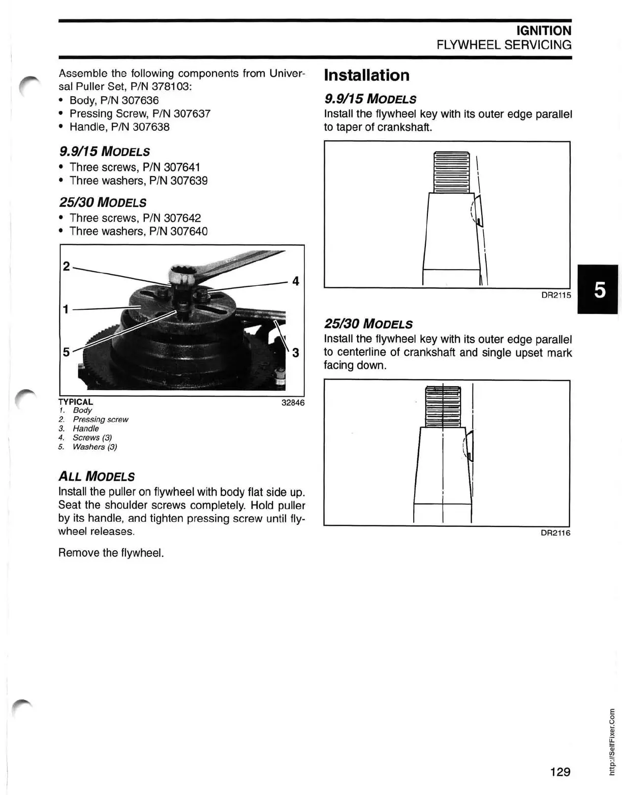
TYPICAL
32846
1. Body
2. Pressing screw
3. Handle
4. Screws (3)
5. Washers (3)
ALL MODELS
Install the puller on flywheel with body flat side up.
Seat the
shoulder screws completely. Hold puller
by its handle, and tighten pressing screw until fly-
wheel releases.
Remove the flywheel.
I
i
I
I
\
\
I
I
I
I
I
I
DR2116
E
o
U
Qj
)(
~
Qj
~
ii
129 E
 Loading...