POWERHEAD
SHIFT LINKAGE
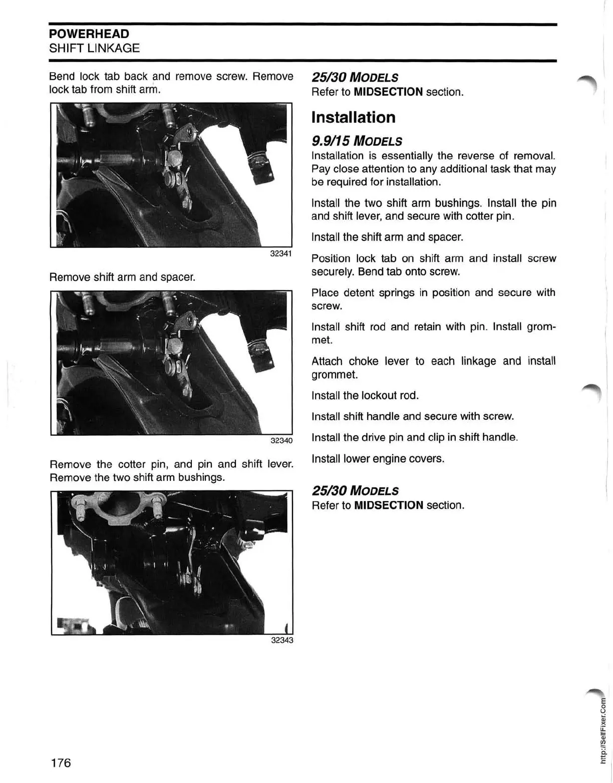
Bend lock tab back and remove screw. Remove 25/30
MODELS
lock tab from shift ann. Refer to MIDSECTION section.
Remove shift arm and spacer.
32340
Remove the cotter pin, and pin and shift lever.
Remove the two shift
arm
bushings.
176
Installation
9.9/15
MODELS
Installation is essentially the reverse of removal.
Pay close attention to any additional task that may
be required for
installation.
Install
the two shift arm bushings. Install the pin
and shift
lever, and secure with cotter pin.
Install the shift arm and spacer.
Position
lock tab
on
shift arm and install screw
securely. Bend tab onto screw.
Place detent springs
in
position and secure with
screw.
Install shift
rod
and retain with pin. Install grom-
met.
Attach choke
lever to each linkage and install
grommet.
Install the lockout rod.
Install shift handle and secure with screw.
Install the drive pin and clip
in
shift handle.
Install lower
engine covers.
25/30
MODELS
Refer to MIDSECTION section.
E
o
U
Qj
)(
~
Qj
~
~
I
 Loading...