POWERHEAD
ASSEMBLY - 25/30
Apply Gasket Sealing Compound to both sides of
a new bypass cover gasket.
Install bypass cover
and tighten the screws
to
a torque of
60
to 84
in.
Ibs
.
(7
to
9 N·
m),
starting with the center screws.
Install the intake manifold and leaf valve assembly
using new gaskets.
Do
not use sealer
on
these
gaskets. Tighten the screws to a torque of
60
to
84
in
.
Ibs.
(7
to
9 N·
m)
.
Install
the fuel, ignition,
and
electrical components
to
the powerhead.
~
WARNING
~
To
prevent
possible fire and
explosion
under
the
engine cover, make sure igni-
tion
and electrical wires are routed and
clamped in original position; away from
rotating parts which could
cut
or
abrade
wire
insulation.
204
ASSEMBLY -
25/30
IMPORTANT: Proceed slowly. Make no forced
assemblies unless a pressing operation is called
for.
All internal components must be perfectly
clean
and
lightly coated with Johnson or Evinrude
Outboard Lubricant.
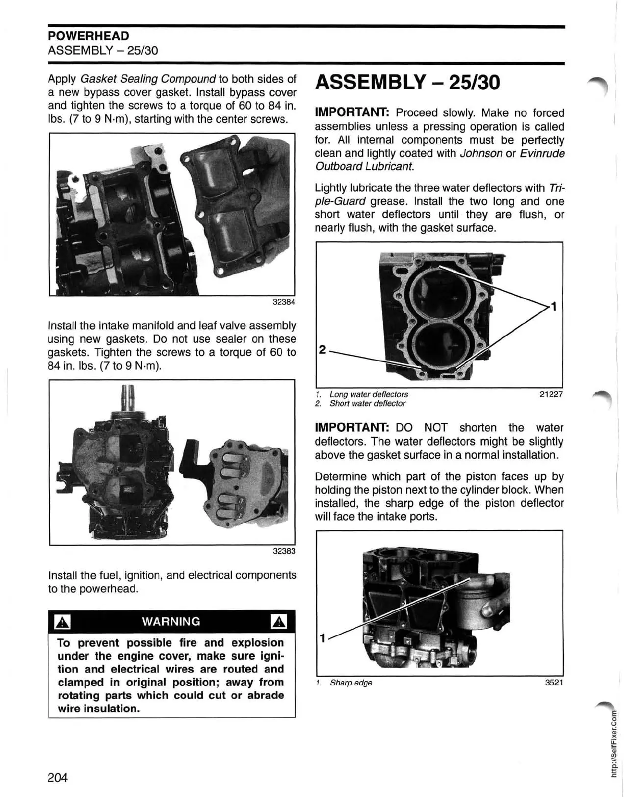
Lightly lubricate the three water deflectors with
Tri-
ple-Guard grease. Install the two long and one
short water deflectors
until they are flush, or
nearly flush, with the gasket surface.
1
2
1. Long water deflectors 21227
2.
Short water deflector
IMPORTANT:
DO
NOT shorten the water
deflectors. The water deflectors might
be
slightly
above the gasket surface
in
a normal installation.
Determine which part of the piston faces up by
holding the piston next
to
the cylinder block. When
installed, the sharp edge of the piston deflector
will face the intake ports.
1
1. Sharp edge
3521
E
o
U
Qj
)(
~
Qj
~
ii
E
 Loading...