Surface Leakage Test
The ignition coil and spark plug lead should
be
tested for leakage or insulation failures using the
ignition
analyzer. Leakage
is
caused by moisture,
cracks, or
holes
in
the coil housing or spark plug
leads.
With the analyzer's black and
red
leads still con-
nected from the Power
Test,
remove the ana-
lyzer's high tension lead from the coil. Turn
on
the
analyzer and probe the entire surfaces of the coil,
spark plug lead, and spark plug cover.
Flashover will
be
apparent wherever insulation
has broken down. Replace any coil or spark plug
lead
which shows leakage.
S.L.O.
W.
WARNING
SYSTEM TESTS
25/30 MODELS
This ignition system incorporates the
S.L.O
w.
™
(Speed Limit Overheat Warning) system, which
limits engine speed to approximately 2000
RPM
if
engine temperature exceeds 180°F (82°C). Once
the
S.L.O
W.
warning system has activated, the
engine must cool to 155°F (68°
C)
and the out-
board must
be
slowed to
an
idle before normal
operation can
be
resumed.
The
S.L.O
W.
warning system depends
on
input
from the temperature switch tan/red
lead.
IGNITION
S.L.O.W. WARNING SYSTEM TESTS
Function Test
Disconnect temperature switch tan/red lead.
Install
correct test propeller. Start outboard
in
test
tank and
run
at 3500
RPM
.
Touch engine harness tan/red
lead to a clean
engine ground.
• If engine speed slows to approximately 2000
RPM (normal operation), test the temperature
switch.
• If engine does not slow to approximately 2000
RPM, check wiring or replace power pack.
IMPORTANT:
On
remote electric start models,
if
the engine goes into S.L.O.
W.
repeatedly or if the I
engine goes into
S.L.O
W.
without
an
operator
warning signal, check the engine harness block-
ing diode. Refer to Blocking Diode Test.
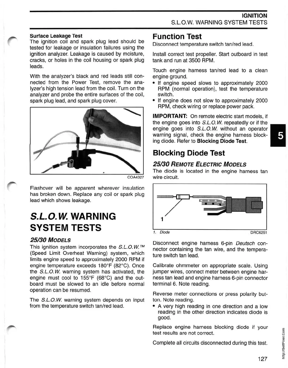
Blocking Diode Test
25/30 REMOTE ELECTRIC MODELS
The diode
is
located
in
the engine harness tan
wire circuit.
1
1. Diode
DRC6251
Disconnect engine harness 6-pin Deutsch con-
nector containing the tan wire, and the tempera-
ture switch tan
lead.
Calibrate
ohmmeter
on
appropriate scale. Using
jumper wires, connect meter between engine har-
ness tan
lead and engine harness 6-pin connector
terminal 6. Note reading.
Reverse meter connections or press polarity but-
ton. Note reading.
• A very high reading
in
one direction and a low
reading
in
the other direction indicates diode
is
good.
Replace engine harness blocking diode if your
test
results are not correct.
Complete all circuits disconnected during this test.
127
E
o
U
Qj
)(
~
Qj
~
ii
E
 Loading...