Home
Johnson
Outboard Motor
J10RSRD
Johnson J10RSRD User Manual
4
of 1
of 1 rating
347 pages
Give review
Manual
Specs
To Next Page
To Next Page
To Previous Page
To Previous Page
Loading...
FUEL
SYSTEM
CARBURETOR
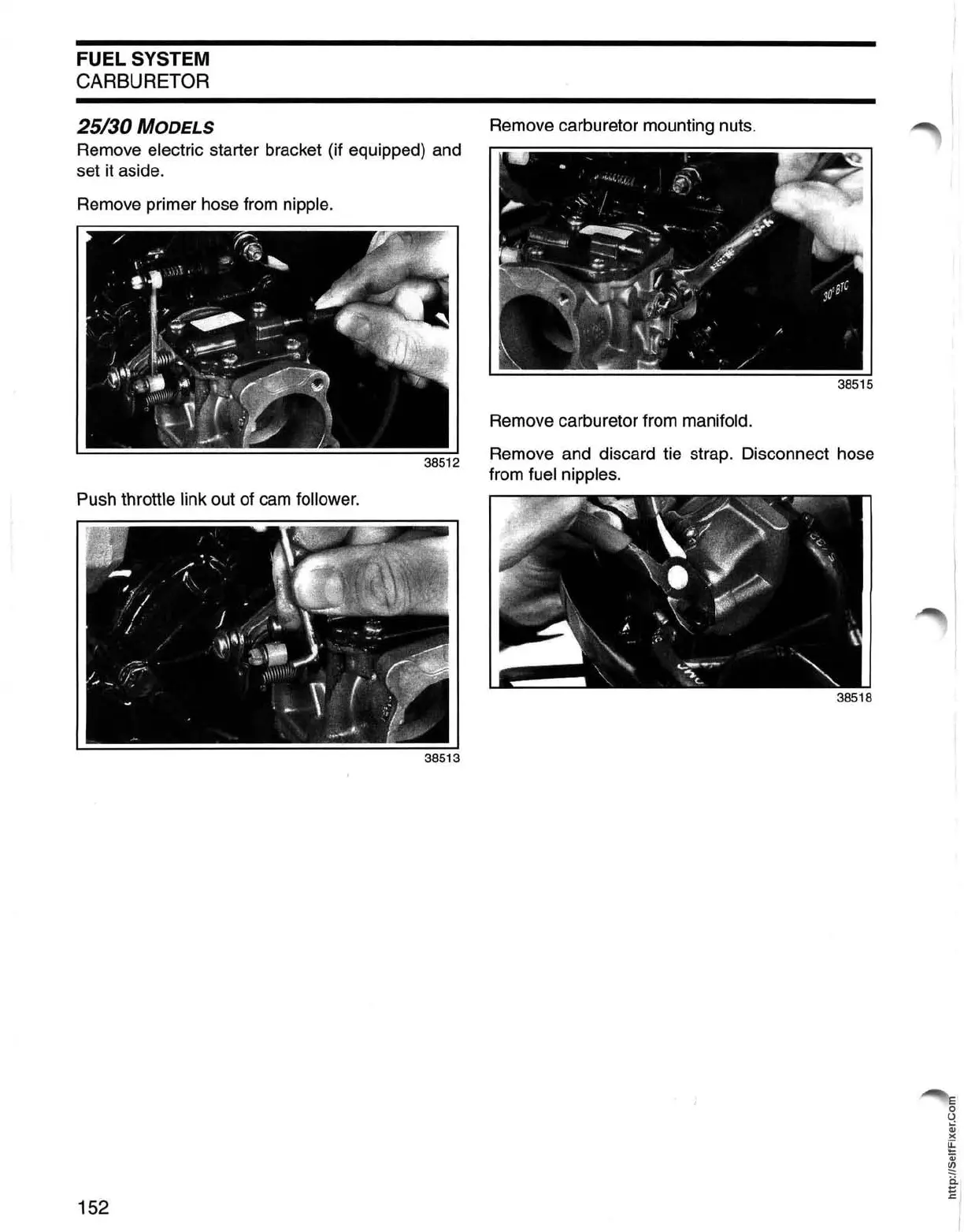
25/30
MODELS
Remove
electric
starter
bracket
(if
equipped)
and
set
it
aside.
Remove
primer
hose
from
nipple.
Push
throttle
link
out
of
cam
follower.
152
Remove
carburetor
mounting
nuts.
Remove
carburetor
from
manifold.
Remove
and
discard
tie
strap.
Disconnect
hose
from
fuel
nipples.
152
154
Table of Contents
Table of Contents
4
Introduction
6
Installation and Predelivery
7
Arrangement of this Manual
7
Models Covered in this Manual
7
Identifying Model and Serial Numbers
7
Model Designation
8
Model List
8
Typical Page - a
9
Typical Page - B
10
Typical Page - C
11
Typical Page - D
12
Abbreviations Used in this Manual
13
Units of Measurement
13
List of Abbreviations
13
Engine Emissions Information
14
Manufacturer's Responsibility
14
Dealer's Responsibility
14
Owner's Responsibility
14
Epa Emission Regulations
14
Product Reference and Illustrations
15
Electrical
15
Values
16
Notes
17
Special Tools and Service Specifications
18
Special Tools
20
Electrical I Ignition
20
Fuel
21
Gearcase
22
Powerhead
24
Starter
25
Universal
25
Shop Aids
28
Technical Data
31
Standard Torque Specifications
33
Installation and Predeliverv
34
Safety Information
36
PREINSTALLATION Considerations
37
Maximum Capacity
37
Mounting Surface
37
Mounting Hardware
37
Transom Measuring and Drilling
38
Inspect Transom Area
38
Measure Transom
38
Transom Drilling
39
Outboard Mounting
40
Fastening the Outboard to the Transom
40
Steering System
40
Remote Controls
41
Remote Control Selection
41
Outboard Rigging Procedure
43
Control Cable Installation
43
Cable, Hose, and Wire Routing
46
Battery and Cables
48
Installing Battery
48
Battery Cable Requirements
48
Fuel Requirements
49
Minimum Octane
49
Additives
49
Fuel System Requirements
50
Overview
50
Fuel Hose
50
Fuel System Primer
50
Fuel Filters
51
Outboard Fuel System Requirements Chart
51
Initial Running Checks
52
Break-In (10 Hours)
53
Fuel System
54
Emergency Stop Ikey Switch
54
Remote Control Operation
54
Start-In-Gear Prevention
54
Tachometer Pulse Setting
54
Water Pump Overboard Indicator
54
Operating Temperature
54
Oil Requirements
52
Engine Lubricant
52
Propeller Selection
55
Procedure
55
Trim Tab Adjustment
56
Notes
57
Maintenance
58
Inspection and Maintenance Schedule
59
Safety Information
62
Anti-Corrosion Protection
63
Sacrificial Anodes
63
Testing Procedure - Continuity
63
Metallic Component Protection
63
Exterior Finishes
63
Cooling System
64
Flushing
64
Water Intake Screens
65
Additional Maintenance
65
Lubrication
66
Steering System
66
Midsection
66
Throttle and Shift Linkage
67
Gearcase Lubricant
68
Propeller Shaft
68
Electric Starter
69
Battery and Battery Connections
69
Fuel System
70
Fuel Filter
70
Air Silencer
70
Hoses and Connections
70
Spark Plugs
70
Synchronization and Linkage Adjustments - 9.9/15
71
Preliminary Adjustments
71
Cam Follower Pickup Point
72
Wide Open Throttle Adjustment
73
Maximum Spark Advance
73
Idle Speed
73
Shift Lever Detent
74
Synchronization and Linkage Adjustments - 25130
74
Cam Follower Pickup Point
74
Throttle Control Rod
75
Maximum Spark Advance
75
Idle Speed
76
Throttle Cable Installation
77
10-Hour Inspection
77
Clamp Screws and Mounting Bolts
77
Storage
78
Fuel System Treatment
78
Internal Engine Treatment
78
Additional Recommendations
78
Pre-Season Service
79
Submerged Engines
79
Notes
81
Electrical
82
Safety
84
Safety Information
84
General
85
Charging System Components
85
Flywheel
85
Rectifier
85
Charging System Tests
86
Charging System Check Chart
86
Running Alternator Output Test
86
Stator Resistance Tests
87
Rectifier Resistance Tests
88
Ac Lighting Coil Resistance Tests
89
Tachometer Circuit Test
90
Electric Starter Tests
91
Start Switch Test
91
Start Circuit Voltage Test
91
Voltage Drop Tests
97
Starter Solenoid Test
98
No Load Current Draw Test
99
Water Temperature Switch Test
100
Electric Starter Servicing
101
Removal
101
Disassembly
101
Cleaning and Inspection
103
Installation
107
Accessory Components
108
General
108
Removal
108
Installation
109
Connector Servicing
110
Amphenol Terminal Removal
110
Amphenol Terminal Installation
111
Ignition
112
Safety Information
114
Components
115
Flywheel
115
Charge Coil
115
Sensor Coil
115
Power Pack
115
Stop Button
116
Key Switch
116
Ignition Coil
117
Peak-Reading Voltmeters
118
Ignition Module Load Adapter
118
Ignition Coil Terminal Extenders
119
Amphenol Connector Adapter
119
Flywheel Holding Tool
119
Troubleshooting
120
Flywheel Indexing
120
Ignition System Tests
121
Total Ignition Output Test
121
Stop Circuit Tests
121
Charge Coil Test
123
Sensor Coil Test
125
Power Pack Cranking Output
125
Power Pack Running Output
126
Ignition Coil Tests
126
S.l.o. W. Warning System Tests
128
Function Test
128
Blocking Diode Test
128
Flywheel Servicing
129
Removal
129
Installation
130
Spark Plugs
129
Ignition Plate Servicing
131
Removal
131
Installation
132
Charge Coil and Sensor Coil
134
Removal
134
Installation
135
Ignition Coil
136
Removal
136
Installation
136
Notes
137
Fuel System
138
Safety Information
140
Components
141
Primer Solenoid
141
Primer Pump
141
Fuel Pump
141
Primer/Fuel Pump
141
Carburetor
142
Intake Manifold
142
Fuel System Trouble Check Chart
143
Fuel System Tests
144
Primer Solenoid Tests
144
Primer Pump Tests
145
Fuel Pump Pressure Test
146
Primer Solenoid
147
Removal
147
Disassembly
147
Assembly
147
Installation
147
Primer Pump
148
Disassembly
148
Cleaning and Inspection
148
Assembly
149
Fuel Pump
150
General
150
Disassembly
150
Cleaning
151
Assembly
151
Carburetor Emissions Compliance
151
Removal
151
25/30 Models Carburetor
153
Disassembly
154
Cleaning and Inspection
155
Assembly
157
Carburetor Mixture Adjustment
162
Intake Manifold
164
Inspection
165
Disassembly
166
Assembly
167
Installation
169
Powerhead
170
Torque Chart
171
Safety Information
172
General
173
Cylinder Compression Testing
173
Retaining Ring Pliers
173
Taper Pin Tool
173
Engine Temperature Check
174
Upper Crankcase Seal
175
General
175
Removal
175
Installation
175
Shift Linkage
176
Removal
176
Installation
177
Adjustment
178
Startswitch
178
Neutral Start Protection
179
Manual Starter
179
Electric Starter
179
Removal - 25130
181
Removal - 9.9/15
181
Disassembly - 9.9/15
185
Disassembly - 25/30
189
Cleaning
194
Inspection
195
All Models
195
Models
196
25/30 Models
197
Assembly - 9.9/15
199
Assembly - 25/30
205
Installation - 9.9/15
214
Installation - 25130
215
Powerhead Views - 9.9/15
218
Port/Starboard View, Manual Start
218
Rear View, Manual Start
219
Powerhead Views - 25/30
220
Port/Starboard View, Manual Start
220
Rear View, Manual Start
221
Port/Starboard View, Tiller Electric Start
222
Rear View, Tiller Electric Start
223
PORT/STARBOARD VIEW, REMOTE Electric
224
Rear View, Remote Electric
225
Midsection
226
Torque Chart
227
Safety Information
228
Steering Handle - Tiller Models
229
Removal
229
Disassembly
231
Inspection
232
Assembly
233
Installation
235
Exhaust Housing
238
Disassembly
238
Cleaning and Inspection
242
General
242
Assembly
243
Swivel Bracket
247
Disassembly
247
Assembly
249
Adjustments
253
Tilt Friction Adjustment
253
Steering Friction Adjustment
253
Idle Speed Adjustment
253
Throttlefriction Adjustment
253
Gearcase
254
Service Chart
255
Safety Information
258
Propeller
259
Inspection
259
Installation
259
Lubricant
260
Draining
260
Inspection
260
Filling
260
Leak Test Procedure
261
Removal and Installation
261
Removal
261
Installation
263
Water Pump
266
Inspection
267
Assembl V
267
25/30 Models Water Pump Assembly
268
Disassembly - 9.9/15
270
Bearing and Seal Removal
274
Driveshaft Seals
274
Driveshaft Bearing
274
Pinion Bearings
275
Forward Bearing
275
Shift Rod Bushing and O-Ring
276
Prop Shaft Bearing Housing Seals and O-Ring
276
Prop Shaft Bearing Housing Bearings
277
Cleaning and Inspection
278
Seal and Bearing Installation
279
Prop Shaft Bearing Housing Bearings
279
Propeller Shaft Bearing Housing Seals and O-Ring
280
Shift Rod Bushing and O-Ring
281
Forward Bearing
281
Pinion Bearings
282
Driveshaft Bearing
282
Driveshaft Seals
283
Assembly - 9.9/15
284
Notes
291
Manual Starter
292
Safety Information
294
General
295
Removal
295
Torque Chart
295
Disassembly
297
Rope Replacement
297
Cleaning and Inspection
299
Assembly
300
Installation
304
Table of Contents
306
Marine Products and the Safety of People Who Use Them
308
Outboard Shift Systems and Safety
309
Outboard Speed Control System and Safety
310
Outboard Steering Control System and Safety
311
Outboard Fuel, Electrical System, and Safety
313
Outboard Mounting System and Safety
316
OUTBOARD HYDRAULIC TILTITRIM SHOCK ABSORPTION SYSTEM and Safety
318
Outboard Emergency Stop System and Safety
319
Summing up
321
Marine Products and the Safety of People Who Fix Them
322
Handling Outboards
322
Handling Lead/Acid Batteries
326
Gasoline - Handle with Care
327
Hazardous Products
328
Safety Awareness Test
329
4
Based on 1 rating
Ask a question
Give review
Questions and Answers:
Need help?
Do you have a question about the Johnson J10RSRD and is the answer not in the manual?
Ask a question
Johnson J10RSRD Specifications
General
Brand
Johnson
Model
J10RSRD
Category
Outboard Motor
Language
English
Related product manuals
Johnson J10RSUR
229 pages
Johnson J10RLSRD
347 pages
Johnson J15RSUA
229 pages
Johnson J15RSRS
347 pages
Johnson J15RLSRS
347 pages
Johnson J30RSRE
347 pages
Johnson J30RLSRE
347 pages
Johnson J30ELSRE
347 pages
Johnson J30MLSRC
347 pages
Johnson J25TELSRA
347 pages
Johnson 115 PL
56 pages
Johnson 6 HORSEPOWER
52 pages
 Loading...