6-S12
L2800, L3400, WSM
FRONT AXLE
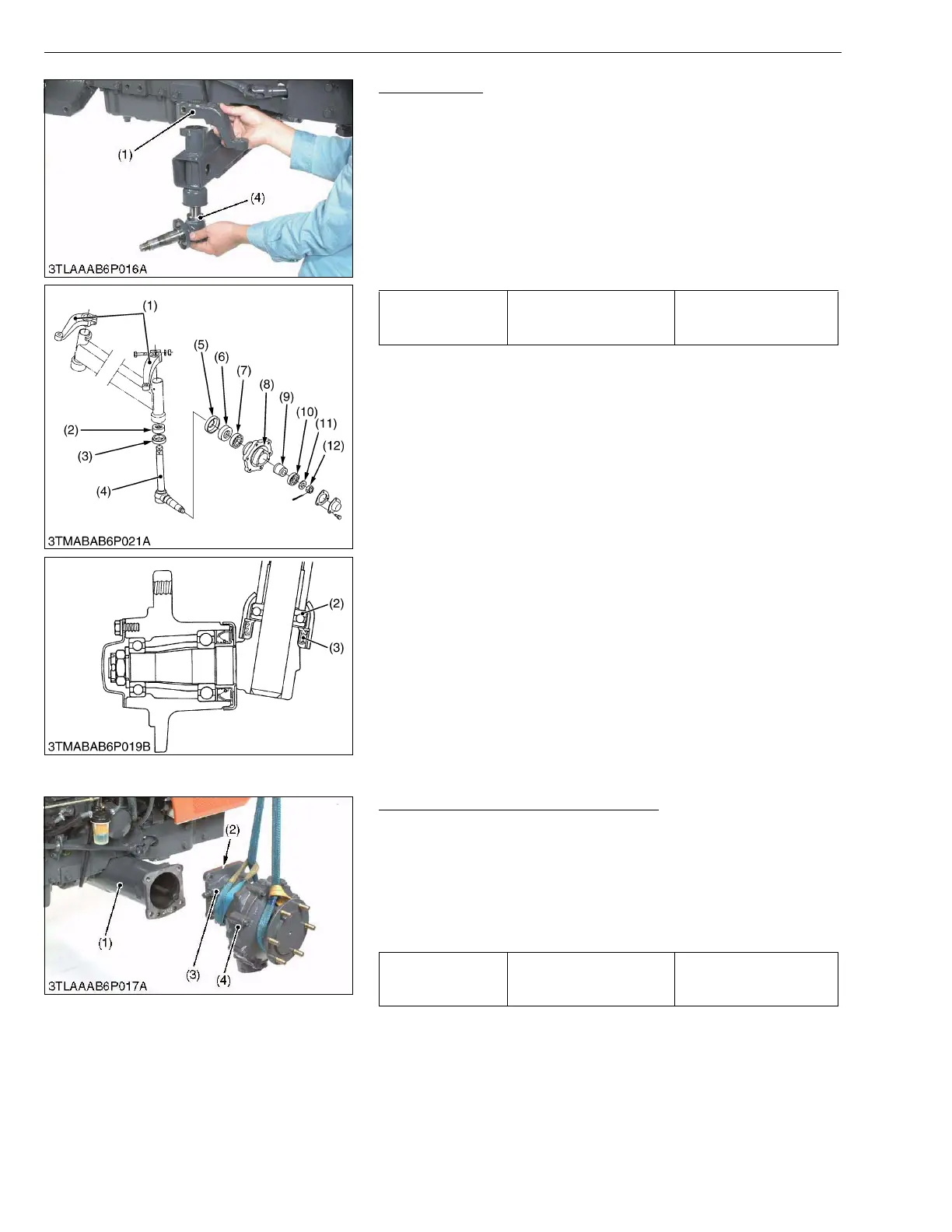
Knuckle Shaft
1. Remove the knuckle arm (1) and draw out the knuckle shaft (4)
from the front axle.
(When reassembling)
• Insert the thrust ball bearing (2) and oil seal (3), noting its
direction.
• Apply grease to the oil seals (3), (6).
• Do not interchange right and left knuckle arms.
• When lift the knuckle shaft, the knuckle arms must be mounted
so that the clearance between the knuckle arms and front axle is
0.3 to 1.0 mm (0.012 to 0.039 in.).
W1014597
(2) 4WD Type Front Axle
Bevel Gear Case and Front Gear Case
1. Remove the bevel gear case mounting screws.
2. Remove the bevel gear case (3) and front gear case (4) as a unit
from the front axle case (1).
(When reassembling)
• Apply grease to the O-ring (2) and take care not to damage it.
• Do not interchange right and left bevel gear case assemblies and
front gear case assemblies.
W1015066
Tightening torque
Knuckle arm mounting bolt
and nut
77.5 to 90.2 N·m
7.9 to 9.2 kgf·m
57.2 to 66.5 ft-lbs
(1) Knuckle Arm
(2) Thrust Ball Bearing
(3) Oil Seal
(4) Knuckle Shaft
(5) Dust Cover
(6) Oil Seal
(7) Ball Bearing
(8) Front Wheel Hub
(9) Spacer
(10) Ball Bearing
(11) Washer
(12) Slotted Nut
Tightening torque
Bevel gear case mounting
screw
123.5 to 147.0 N·m
12.6 to 15.0 kgf·m
91.2 to 108.4 ft-lbs
(1) Front Axle Case
(2) O-ring
(3) Bevel Gear Case
(4) Front Gear Case
Tractor Manuals Scotland - Please Do Not Copy

 Loading...


