8-S21
L2800, L3400, WSM
HYDRAULIC SYSTEM
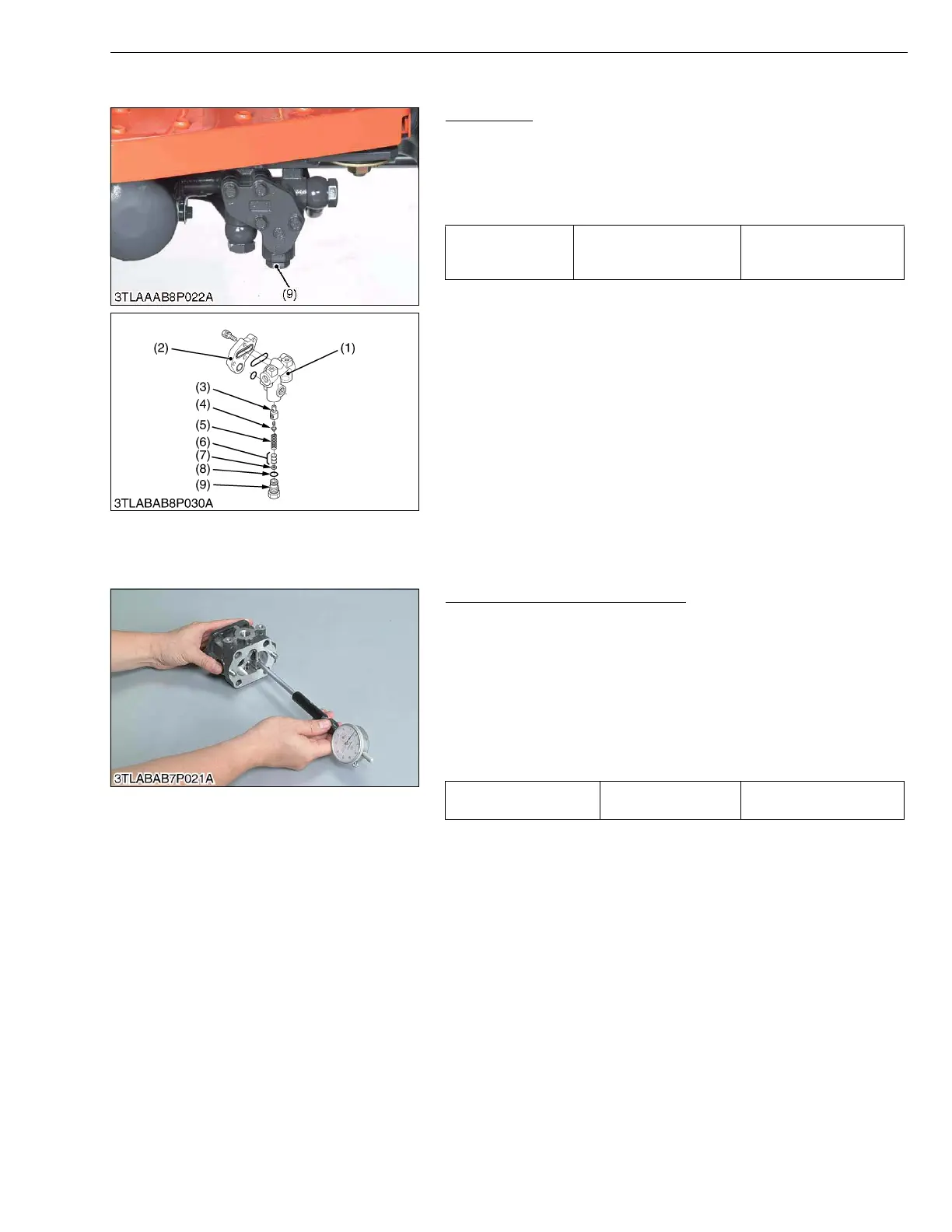
(5) Relief Valve
Relief Valve
1. Remove the plug (9), and draw out the spring (5) and the poppet
(4).
2. Take out the valve seat (3).
(When reassembling)
• Take care not to damage the O-ring.
• After disassembling and assembling the relief valve, be sure
to adjust the relief valve setting pressure.
W1022485
[3] SERVICING
(1) Hydraulic Pump (Power Steering)
Housing Bore (Depth of Scratch)
1. Check for the scratch on the interior surface of the housing
caused by the gear.
2. If the scratch reaches more than half the area of the interior
surface of the housing, replace at pump assembly.
3. Measure the housing I.D. where the interior surface is not
scratched, and measure the housing I.D. where the interior
surface is scratched.
4. If the valves obtained in the two determinations differ by more
than the allowable limit, replace the hydraulic pump as a unit.
(Reference)
• Use a cylinder gauge to measure the housing I.D.
W1014649
Tightening torque Relief valve plug
49.0 to 69.0 N·m
5.0 to 7.0kgf·m
36.1 to 50.6 ft-lbs
(1) Front Hydraulic Block
(2) Cap
(3) Valve Seat
(4) Poppet
(5) Spring
(6) Adjusting Shim
(7) Washer
(8) O-ring
(9) Plug
Depth of scratch Allowable limit
0.09 mm
0.0035 in.
Tractor Manuals Scotland - Please Do Not Copy

 Loading...


