8-M1
L2800, L3400, WSM
HYDRAULIC SYSTEM
1. HYDRAULIC CIRCUIT
W1013328
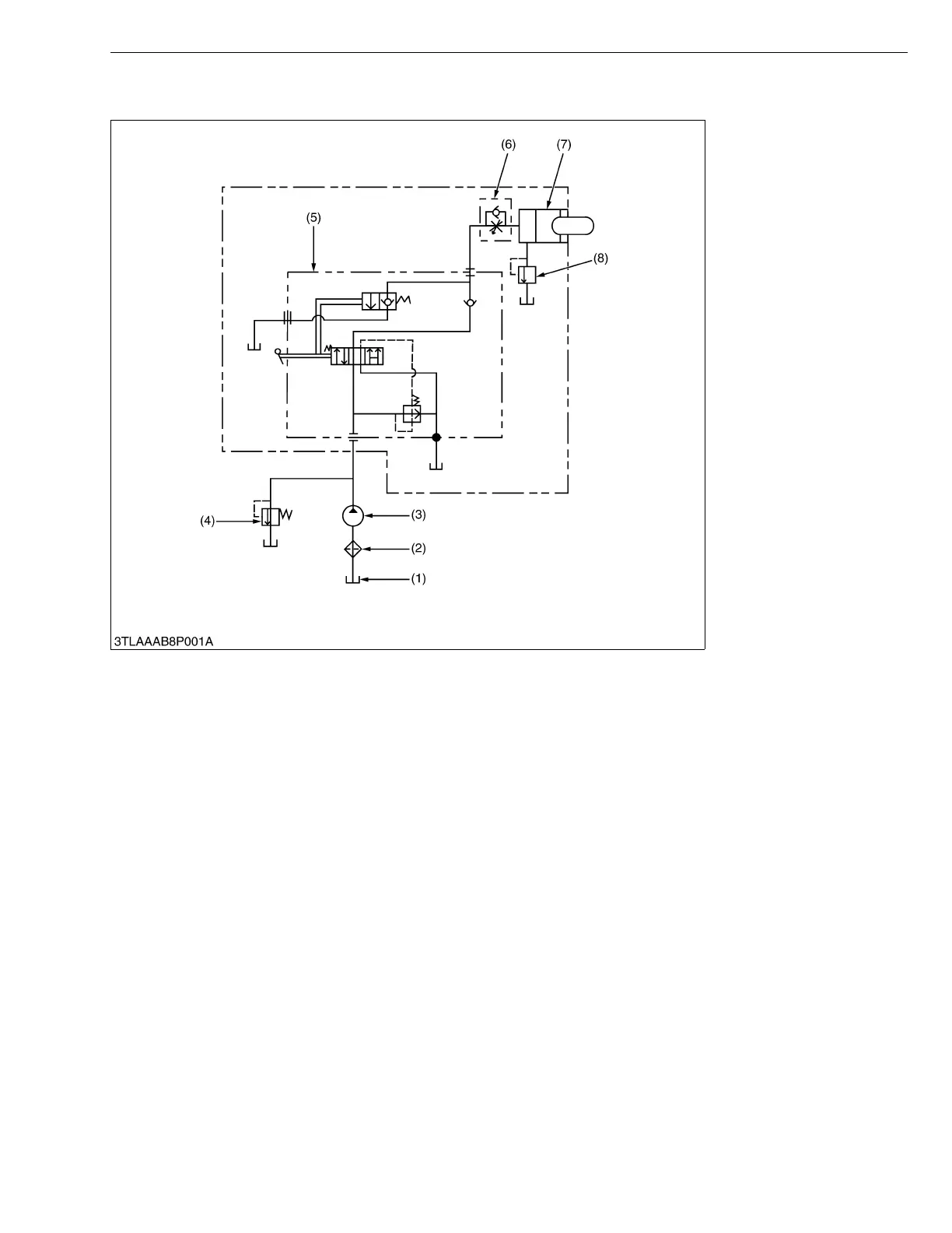
■ Hydraulic Oil Flow
1. When the engine is started, the hydraulic pump (3) is rotated to draw oil from the transmission case (1) through the
suction pipe. Supplied oil is filtered by the oil strainer (2).
2. Filtered oil is forced out by the hydraulic pump to the position control valve (5) through the delivery pipe.
3. The position control valve (5) switches the oil flow, and oil is channelled to the hydraulic cylinder (7) for the three-
point hydraulic system or returned to the oil tank (transmission case).
• The hydraulic system has a relief valve (4) which restricts the maximum pressure in the circuit.
(1) Oil Tank
(Transmission Case)
(2) Oil Strainer
(3) Hydraulic Pump
(4) Relief Valve
(5) Position Control Valve
(6) Lowering Speed Adjusting
Valve
(7) Hydraulic Cylinder
(8) Cylinder Safety Valve
Tractor Manuals Scotland - Please Do Not Copy

 Loading...


