EasyManua.ls Logo

Mitsubishi Electric MELSEC-Q00U(J)CPU User Manual

Mitsubishi Electric MELSEC-Q00U(J)CPU
588 pages
To Next Page IconTo Next Page
To Previous Page IconTo Previous Page
Page #161 background imageLoading...
Page #161 background image
159
CHAPTER 3 FUNCTIONS
3
3.11 Monitor Function
3.11.4 Executional conditioned device test
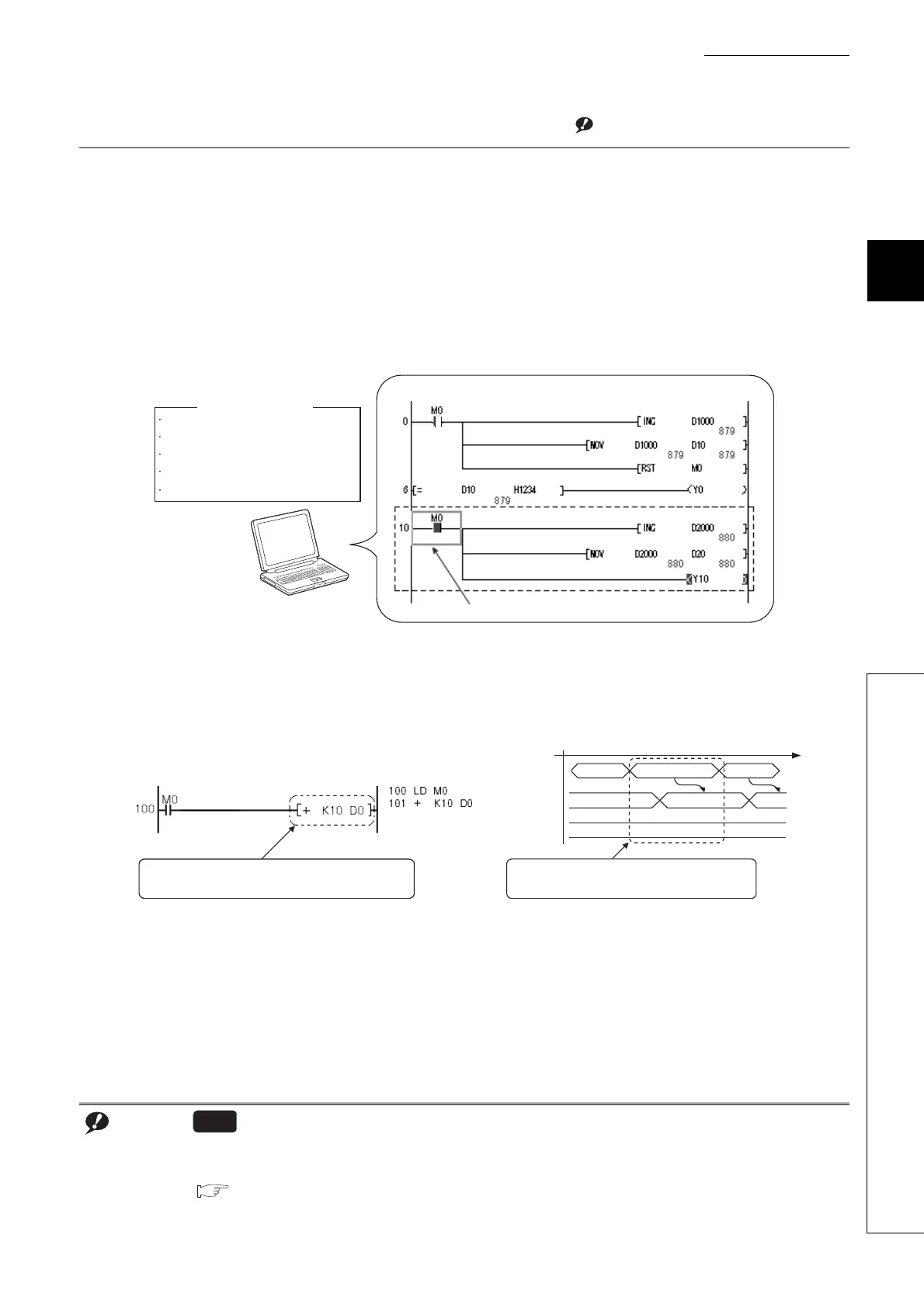
This function changes a device value within the specified step of a program.Note 3.5
This enables debugging of the specified ladder block without modifying the program.
*1
*1 The executional conditioned device test is not available for the SFC program.
(1) Operation of the executional conditioned device test
A device value will be changed based on the registration data once after the executional conditioned device test
setting is registered.
The changed device value becomes enabled in the ladder blocks of the specified step number and later.
Note that a device value is changed within the specified step regardless of an execution status of the instruction in
the specified step.
Note 3.5
Before executing the function with the Q02UCPU, Q03UDCPU, Q04UDHCPU, Q06UDHCPU, Q13UDHCPU, or
Q26UDHCPU, check the versions of the CPU module and programming tool used.
( Page 465, Appendix 2)
Note 3.5
Universal
Programming tool
Program name
Step No.
Device
Setting value
Execution timing
: MAIN
: 10
: M0
: ON
: Before executing instruction
Registration data
M0 is turned on.
Program: MAIN
<Program example> <Operation>
Processing
LD M0
10 35
OFF
45
Changes the value in D0 to "35".
+ K10 D0
Value in D0
Value in M0
Executional conditioned device test which
sets "35" in D0 in this step is registered.
A device value is changed within the
specified step regardless of the value in M0.
List mode
Ladder mode

Table of Contents

Question and Answer IconNeed help?

Do you have a question about the Mitsubishi Electric MELSEC-Q00U(J)CPU and is the answer not in the manual?

Mitsubishi Electric MELSEC-Q00U(J)CPU Specifications

General IconGeneral
SeriesMELSEC-Q
ModelQ00U(J)CPU
Power supply voltage24 VDC
Operating temperature0 to 55 °C
Number of I/O Points4096 points
Programming LanguageLadder, Instruction list, SFC, Function block, Structured text
Execution Speed (LD instruction)0.08 µs
Dimensions90 x 90 x 90 mm
Weight0.5 kg
Processing speed0.08 µs
Built-in portsRS-232
CommunicationEthernet, Serial
TypeProgrammable Logic Controller (PLC)

Summary

SAFETY PRECAUTIONS

Design Precautions

Configure external safety circuits and understand output status upon fault detection for system safety and reliability.

CONDITIONS OF USE FOR THE PRODUCT

INTRODUCTION

MANUALS

CPU module user's manual

Details specifications, functions, maintenance, troubleshooting, and error codes of CPU modules.

Programming manual

Describes instructions, programming, and error codes for various programming languages like SFC.

MANUAL PAGE ORGANIZATION

TERMS

PART 1 PROGRAMMING

CHAPTER 1 BASIC PROCEDURE FOR PROGRAMMING

Covers fundamental programming steps: project creation, program creation, conversion, writing, checking, and saving.

CHAPTER 2 APPLICATION OF PROGRAMMING

Details programming concepts like memory, files, base units, I/O assignment, and scan time structure.

PART 2 FUNCTIONS

CHAPTER 3 FUNCTIONS

Describes various functions of the Universal model QCPU, including lists, operations, and settings.

CHAPTER 4 DEVICES

4.1 Device List

Lists all internal user devices, internal system devices, link direct devices, and other devices with their points and ranges.

4.2 Internal User Devices

Details internal user devices like input (X), output (Y), internal relay (M), latch relay (L), annunciator (F), edge relay (V), timers, counters, registers.

4.3 Internal System Devices

Describes fixed internal system devices like function devices (FX, FY, FD), special relays (SM), and special registers (SD).

4.4 Link Direct Device

Explains direct access to link devices in CC-Link IE, MELSECNET/H modules, and their specification methods.

4.5 Module Access Devices

Details intelligent function module device and cyclic transmission area device for accessing buffer memory and shared memory.

4.6 Index Register (Z)/Standard Device Resister (Z)

Explains index registers for indirect specification and standard device registers for higher speed operations.

4.7 File Register (R)

Describes file register usage, storage location, size, differences from link refresh, and registration procedures.

4.8 Extended Data Register (D) and Extended Link Register (W)

Explains extended data and link registers as extensions to data and link registers, using file register area.

4.9 Nesting (N)

Details nesting (N) device used with master control instructions for programming operation conditions.

4.10 Pointer (P)

Explains pointers used for jump and subroutine call instructions, including local and common pointer types.

4.11 Interrupt Pointer(I)

Describes interrupt pointers for starting interrupt programs and lists available interrupt factors and their priorities.

4.12 Other Devices

Covers SFC block devices (BL), Network No. specification devices (J), I/O No. specification devices (U), and Macro instruction argument devices (VD).

CHAPTER 5 CONSTANTS

5.1 Decimal Constant (K)

Specifies decimal data in sequence programs using the 'K' notation.

5.2 Hexadecimal Constant (H)

Specifies hexadecimal or BCD data in sequence programs using the 'H' notation.

5.3 Real Number (E)

Specifies real numbers in sequence programs using the 'E' notation for floating-point data.

5.4 Character String (" ")

Specifies character strings in sequence programs using characters enclosed in quotation marks.

CHAPTER 6 CONVENIENT USAGE OF DEVICES

6.1 Global Device

Describes global devices that can be shared by multiple programs, stored in CPU module device memory.

6.2 Local Device

Explains local devices used independently for each program, allowing multiple programs without conflicts.

APPENDICES

Appendix 1 Parameters

Details parameters for programmable controller systems, including PLC, Network, and Remote Password settings.

Appendix 2 Functions Added or Changed by Version Upgrade

Lists functions added or changed based on CPU module and programming tool versions.

Appendix 3 CPU Module Processing Time

Describes scan time structures and CPU module processing times for various operations.

Appendix 4 Data Used in Sequence Programs

Explains numeric representations like BIN, HEX, BCD, and real numbers used in sequence programs.

Appendix 5 Replacing Basic Model QCPU or Qn(H)CPU with QnUCPU

Provides precautions and methods for replacing basic or high performance QCPU with Universal model QCPU.

Appendix 6 Precautions for Replacing QnUD(E)(H)CPU with QnUDVCPU/QnUDPVCPU

Details precautions and replacement methods when migrating from QnUD(E)(H)CPU to QnUDVCPU/QnUDPVCPU.

Appendix 7 Precautions for Replacing QnPHCPU with QnUDPVCPU

Provides precautions for replacing QnPHCPU with QnUDPVCPU.

Appendix 8 Precautions for Using GX Works2 and Differences with GX Developer

Covers precautions and differences when using GX Works2 versus GX Developer.

Appendix 9 Ways to Use Different Types of the Backup/restoration Function

Explains how to use various types of backup/restoration functions for GOT and CPU modules.

REVISIONS

WARRANTY

Related product manuals