EasyManua.ls Logo

Mitsubishi Electric MELSEC-Q00U(J)CPU User Manual

Mitsubishi Electric MELSEC-Q00U(J)CPU
588 pages
To Next Page IconTo Next Page
To Previous Page IconTo Previous Page
Page #191 background imageLoading...
Page #191 background image
189
CHAPTER 3 FUNCTIONS
3
3.15 Debug from Multiple Programming Tools
This function allows simultaneous debugging from multiple programming tools connected to modules (such as a CPU
module and serial communication module). This function is useful when debugging multiple files divided according to
processes or functions.
(1) Description
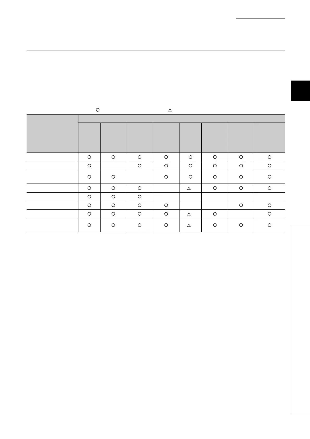
The following table lists the combinations of functions that can be executed simultaneously using this function.
: Can be simultaneously performed, : Partially restricted, × : Cannot be simultaneously performed
*1 This includes a ladder monitor, device batch monitor, entry data monitor, entry ladder monitor, and local device monitor.
*2 Cannot be performed simultaneously when the step number, or the step number and device number, are set in the
monitor condition.
*3 Cannot be performed simultaneously unless the step number is set to the trace point or the trigger point.
*4 Cannot be performed simultaneously in the following cases.
The data to be changed online includes the registration of an executional conditioned device test.
When adding a ladder block by online change, registration of an executional conditioned device test is included in
the ladder block immediately after the one where the ladder block is to be added.
The program to be changed online includes registration of an executional conditioned device test.
Function in
execution
Function executed later
Monitor
*1
Program
monitor
list
Interrupt
program
monitor
list
Monitor
condition
setting
Online
change
Scan time
measure
ment
Sampling
trace
Executional
conditioned
device test
monitor
*1
Program monitor list ×
Interrupt program monitor
list
×
Monitor condition setup ×
*2
Online change × × × × ×
Scan time measurement × ×
Sampling trace
*3
×
Executional conditioned
device test
*4

Table of Contents

Question and Answer IconNeed help?

Do you have a question about the Mitsubishi Electric MELSEC-Q00U(J)CPU and is the answer not in the manual?

Mitsubishi Electric MELSEC-Q00U(J)CPU Specifications

General IconGeneral
SeriesMELSEC-Q
ModelQ00U(J)CPU
Power supply voltage24 VDC
Operating temperature0 to 55 °C
Number of I/O Points4096 points
Programming LanguageLadder, Instruction list, SFC, Function block, Structured text
Execution Speed (LD instruction)0.08 µs
Dimensions90 x 90 x 90 mm
Weight0.5 kg
Processing speed0.08 µs
Built-in portsRS-232
CommunicationEthernet, Serial
TypeProgrammable Logic Controller (PLC)

Summary

SAFETY PRECAUTIONS

Design Precautions

Configure external safety circuits and understand output status upon fault detection for system safety and reliability.

CONDITIONS OF USE FOR THE PRODUCT

INTRODUCTION

MANUALS

CPU module user's manual

Details specifications, functions, maintenance, troubleshooting, and error codes of CPU modules.

Programming manual

Describes instructions, programming, and error codes for various programming languages like SFC.

MANUAL PAGE ORGANIZATION

TERMS

PART 1 PROGRAMMING

CHAPTER 1 BASIC PROCEDURE FOR PROGRAMMING

Covers fundamental programming steps: project creation, program creation, conversion, writing, checking, and saving.

CHAPTER 2 APPLICATION OF PROGRAMMING

Details programming concepts like memory, files, base units, I/O assignment, and scan time structure.

PART 2 FUNCTIONS

CHAPTER 3 FUNCTIONS

Describes various functions of the Universal model QCPU, including lists, operations, and settings.

CHAPTER 4 DEVICES

4.1 Device List

Lists all internal user devices, internal system devices, link direct devices, and other devices with their points and ranges.

4.2 Internal User Devices

Details internal user devices like input (X), output (Y), internal relay (M), latch relay (L), annunciator (F), edge relay (V), timers, counters, registers.

4.3 Internal System Devices

Describes fixed internal system devices like function devices (FX, FY, FD), special relays (SM), and special registers (SD).

4.4 Link Direct Device

Explains direct access to link devices in CC-Link IE, MELSECNET/H modules, and their specification methods.

4.5 Module Access Devices

Details intelligent function module device and cyclic transmission area device for accessing buffer memory and shared memory.

4.6 Index Register (Z)/Standard Device Resister (Z)

Explains index registers for indirect specification and standard device registers for higher speed operations.

4.7 File Register (R)

Describes file register usage, storage location, size, differences from link refresh, and registration procedures.

4.8 Extended Data Register (D) and Extended Link Register (W)

Explains extended data and link registers as extensions to data and link registers, using file register area.

4.9 Nesting (N)

Details nesting (N) device used with master control instructions for programming operation conditions.

4.10 Pointer (P)

Explains pointers used for jump and subroutine call instructions, including local and common pointer types.

4.11 Interrupt Pointer(I)

Describes interrupt pointers for starting interrupt programs and lists available interrupt factors and their priorities.

4.12 Other Devices

Covers SFC block devices (BL), Network No. specification devices (J), I/O No. specification devices (U), and Macro instruction argument devices (VD).

CHAPTER 5 CONSTANTS

5.1 Decimal Constant (K)

Specifies decimal data in sequence programs using the 'K' notation.

5.2 Hexadecimal Constant (H)

Specifies hexadecimal or BCD data in sequence programs using the 'H' notation.

5.3 Real Number (E)

Specifies real numbers in sequence programs using the 'E' notation for floating-point data.

5.4 Character String (" ")

Specifies character strings in sequence programs using characters enclosed in quotation marks.

CHAPTER 6 CONVENIENT USAGE OF DEVICES

6.1 Global Device

Describes global devices that can be shared by multiple programs, stored in CPU module device memory.

6.2 Local Device

Explains local devices used independently for each program, allowing multiple programs without conflicts.

APPENDICES

Appendix 1 Parameters

Details parameters for programmable controller systems, including PLC, Network, and Remote Password settings.

Appendix 2 Functions Added or Changed by Version Upgrade

Lists functions added or changed based on CPU module and programming tool versions.

Appendix 3 CPU Module Processing Time

Describes scan time structures and CPU module processing times for various operations.

Appendix 4 Data Used in Sequence Programs

Explains numeric representations like BIN, HEX, BCD, and real numbers used in sequence programs.

Appendix 5 Replacing Basic Model QCPU or Qn(H)CPU with QnUCPU

Provides precautions and methods for replacing basic or high performance QCPU with Universal model QCPU.

Appendix 6 Precautions for Replacing QnUD(E)(H)CPU with QnUDVCPU/QnUDPVCPU

Details precautions and replacement methods when migrating from QnUD(E)(H)CPU to QnUDVCPU/QnUDPVCPU.

Appendix 7 Precautions for Replacing QnPHCPU with QnUDPVCPU

Provides precautions for replacing QnPHCPU with QnUDPVCPU.

Appendix 8 Precautions for Using GX Works2 and Differences with GX Developer

Covers precautions and differences when using GX Works2 versus GX Developer.

Appendix 9 Ways to Use Different Types of the Backup/restoration Function

Explains how to use various types of backup/restoration functions for GOT and CPU modules.

REVISIONS

WARRANTY

Related product manuals