EasyManua.ls Logo

Mitsubishi Electric MELSEC-Q00U(J)CPU User Manual

Mitsubishi Electric MELSEC-Q00U(J)CPU
588 pages
To Next Page IconTo Next Page
To Previous Page IconTo Previous Page
Page #496 background imageLoading...
Page #496 background image
494
Appendix 4.1 BIN (Binary Code)
(1) Definition
Binary is a numeral system that represents numeric values using two symbols, 0 (off) and 1 (on).
Decimal notation uses the symbols 0 through 9. When the symbols for the first digit are exhausted (a digit
reaches 9), the next-higher digit (to the left) is incremented, and counting starts over at 0.
In binary notation, only the symbols 0 and 1 are used. After a digit reaches 1, an increment resets it to 0 and the
next digit (to the left) is incremented. (The numeric value becomes 10, which is equal to 2 in decimal.)
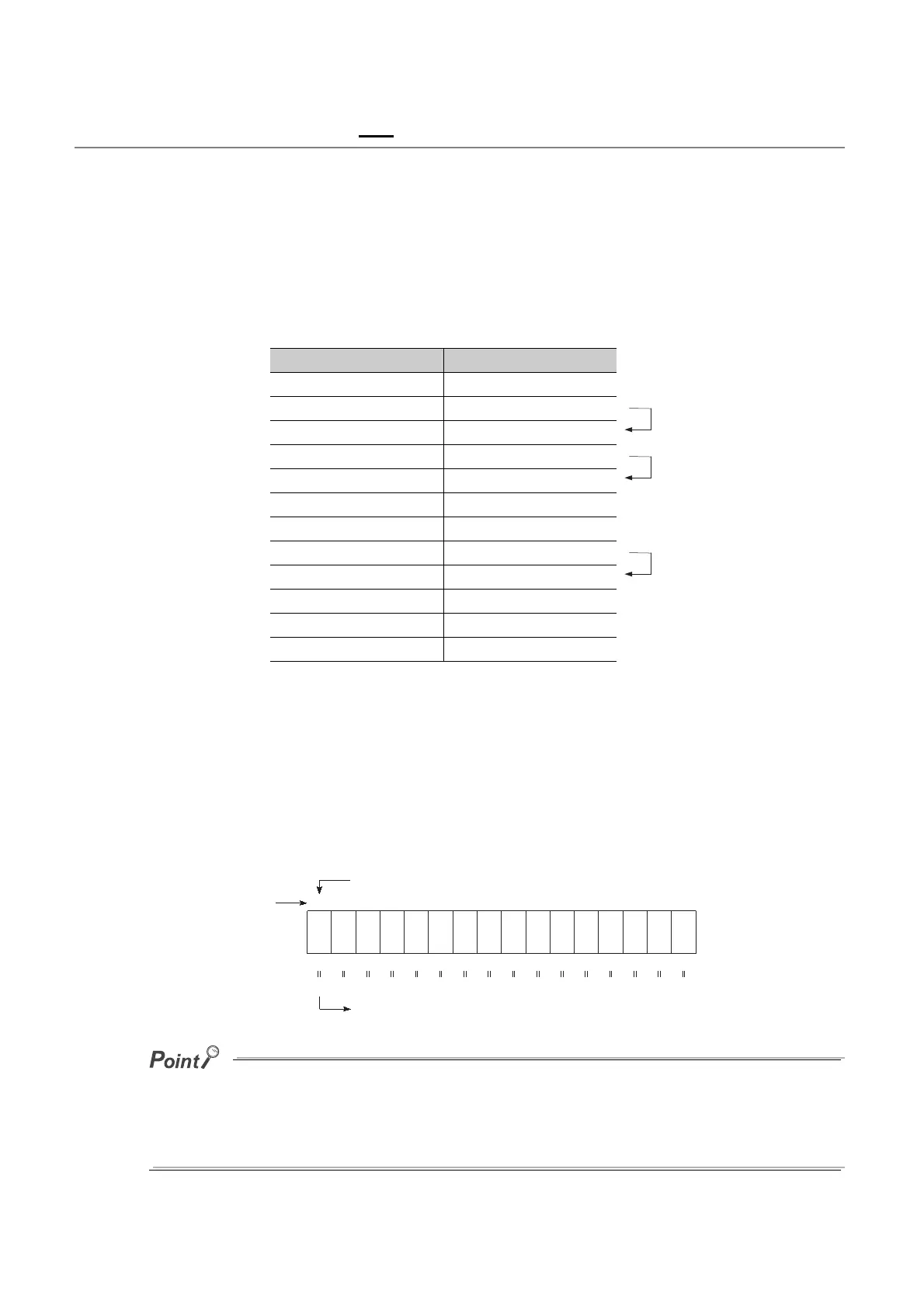
The following table lists the numeric representations in BIN and DEC.
(2) Numeric representation in BIN
(a) Bit configuration of BIN used in the CPU module
Each register (such as the data register, link register) in the CPU module consists of 16 bits.
(b) Numeric data available in the CPU module
Each register in the CPU module can store numeric values in the range of -32768 to 32767.
The following figure shows the numeric representations for registers.
A numeric value of 2
n
is assigned for each bit of registers.
Note that an unsigned binary number (0 to 65535) cannot be used in the most significant bit position since the most
significant bit is a sign bit.
The most significant bit is "0"...Positive
The most significant bit is "1"...Negative
DEC (Decimal) BIN (Binary)
00000
10001
20010
3 0011
40100
50101
60110
7 0111
81000
91001
10 1010
11 1011
Carry
Carry
Carry
b15
8192
Bit name
Decimal value
Most significant bit (sign bit)
A value will be negative value when the most significant bit is "1".
16384
4096 2048 1024 512 256 128 64 32 16 8 4 2 1
-32768
2
15
2
14
2
13
2
12
2
11
2
10
2
9
2
8
2
7
2
6
2
5
2
4
2
3
2
2
2
1
2
0
b14 b13 b12 b11 b10 b9 b8 b7 b6 b5 b4 b3 b2 b1 b0

Table of Contents

Question and Answer IconNeed help?

Do you have a question about the Mitsubishi Electric MELSEC-Q00U(J)CPU and is the answer not in the manual?

Mitsubishi Electric MELSEC-Q00U(J)CPU Specifications

General IconGeneral
SeriesMELSEC-Q
ModelQ00U(J)CPU
Power supply voltage24 VDC
Operating temperature0 to 55 °C
Number of I/O Points4096 points
Programming LanguageLadder, Instruction list, SFC, Function block, Structured text
Execution Speed (LD instruction)0.08 µs
Dimensions90 x 90 x 90 mm
Weight0.5 kg
Processing speed0.08 µs
Built-in portsRS-232
CommunicationEthernet, Serial
TypeProgrammable Logic Controller (PLC)

Summary

SAFETY PRECAUTIONS

Design Precautions

Configure external safety circuits and understand output status upon fault detection for system safety and reliability.

CONDITIONS OF USE FOR THE PRODUCT

INTRODUCTION

MANUALS

CPU module user's manual

Details specifications, functions, maintenance, troubleshooting, and error codes of CPU modules.

Programming manual

Describes instructions, programming, and error codes for various programming languages like SFC.

MANUAL PAGE ORGANIZATION

TERMS

PART 1 PROGRAMMING

CHAPTER 1 BASIC PROCEDURE FOR PROGRAMMING

Covers fundamental programming steps: project creation, program creation, conversion, writing, checking, and saving.

CHAPTER 2 APPLICATION OF PROGRAMMING

Details programming concepts like memory, files, base units, I/O assignment, and scan time structure.

PART 2 FUNCTIONS

CHAPTER 3 FUNCTIONS

Describes various functions of the Universal model QCPU, including lists, operations, and settings.

CHAPTER 4 DEVICES

4.1 Device List

Lists all internal user devices, internal system devices, link direct devices, and other devices with their points and ranges.

4.2 Internal User Devices

Details internal user devices like input (X), output (Y), internal relay (M), latch relay (L), annunciator (F), edge relay (V), timers, counters, registers.

4.3 Internal System Devices

Describes fixed internal system devices like function devices (FX, FY, FD), special relays (SM), and special registers (SD).

4.4 Link Direct Device

Explains direct access to link devices in CC-Link IE, MELSECNET/H modules, and their specification methods.

4.5 Module Access Devices

Details intelligent function module device and cyclic transmission area device for accessing buffer memory and shared memory.

4.6 Index Register (Z)/Standard Device Resister (Z)

Explains index registers for indirect specification and standard device registers for higher speed operations.

4.7 File Register (R)

Describes file register usage, storage location, size, differences from link refresh, and registration procedures.

4.8 Extended Data Register (D) and Extended Link Register (W)

Explains extended data and link registers as extensions to data and link registers, using file register area.

4.9 Nesting (N)

Details nesting (N) device used with master control instructions for programming operation conditions.

4.10 Pointer (P)

Explains pointers used for jump and subroutine call instructions, including local and common pointer types.

4.11 Interrupt Pointer(I)

Describes interrupt pointers for starting interrupt programs and lists available interrupt factors and their priorities.

4.12 Other Devices

Covers SFC block devices (BL), Network No. specification devices (J), I/O No. specification devices (U), and Macro instruction argument devices (VD).

CHAPTER 5 CONSTANTS

5.1 Decimal Constant (K)

Specifies decimal data in sequence programs using the 'K' notation.

5.2 Hexadecimal Constant (H)

Specifies hexadecimal or BCD data in sequence programs using the 'H' notation.

5.3 Real Number (E)

Specifies real numbers in sequence programs using the 'E' notation for floating-point data.

5.4 Character String (" ")

Specifies character strings in sequence programs using characters enclosed in quotation marks.

CHAPTER 6 CONVENIENT USAGE OF DEVICES

6.1 Global Device

Describes global devices that can be shared by multiple programs, stored in CPU module device memory.

6.2 Local Device

Explains local devices used independently for each program, allowing multiple programs without conflicts.

APPENDICES

Appendix 1 Parameters

Details parameters for programmable controller systems, including PLC, Network, and Remote Password settings.

Appendix 2 Functions Added or Changed by Version Upgrade

Lists functions added or changed based on CPU module and programming tool versions.

Appendix 3 CPU Module Processing Time

Describes scan time structures and CPU module processing times for various operations.

Appendix 4 Data Used in Sequence Programs

Explains numeric representations like BIN, HEX, BCD, and real numbers used in sequence programs.

Appendix 5 Replacing Basic Model QCPU or Qn(H)CPU with QnUCPU

Provides precautions and methods for replacing basic or high performance QCPU with Universal model QCPU.

Appendix 6 Precautions for Replacing QnUD(E)(H)CPU with QnUDVCPU/QnUDPVCPU

Details precautions and replacement methods when migrating from QnUD(E)(H)CPU to QnUDVCPU/QnUDPVCPU.

Appendix 7 Precautions for Replacing QnPHCPU with QnUDPVCPU

Provides precautions for replacing QnPHCPU with QnUDPVCPU.

Appendix 8 Precautions for Using GX Works2 and Differences with GX Developer

Covers precautions and differences when using GX Works2 versus GX Developer.

Appendix 9 Ways to Use Different Types of the Backup/restoration Function

Explains how to use various types of backup/restoration functions for GOT and CPU modules.

REVISIONS

WARRANTY

Related product manuals