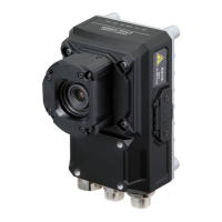
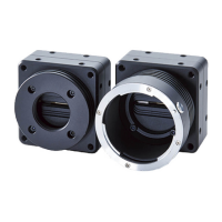
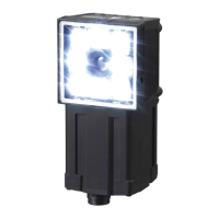
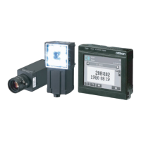
FQ2 User’s Manual
9
Table of Contents
Table of Contents
1. Introduction
1-1 FQ2-series Vision Sensors. . . . . . . . . . . . . . . . . . . . . . . . . . . . . . . . . . . . . 20
1-2 Measurement Process . . . . . . . . . . . . . . . . . . . . . . . . . . . . . . . . . . . . . . . . 21
1-3 Startup Display and Display Elements . . . . . . . . . . . . . . . . . . . . . . . . . . . 22
Startup Display . . . . . . . . . . . . . . . . . . . . . . . . . . . . . . . . . . . . . . . . . . . . . . . . . 22
Display Elements . . . . . . . . . . . . . . . . . . . . . . . . . . . . . . . . . . . . . . . . . . . . . . . .23
1-4 Basic Operational Flow. . . . . . . . . . . . . . . . . . . . . . . . . . . . . . . . . . . . . . . . 24
2. Installation and Connections
2-1 System Configuration. . . . . . . . . . . . . . . . . . . . . . . . . . . . . . . . . . . . . . . . . 26
2-2 Part Names and Functions. . . . . . . . . . . . . . . . . . . . . . . . . . . . . . . . . . . . . 29
2-3 Installation . . . . . . . . . . . . . . . . . . . . . . . . . . . . . . . . . . . . . . . . . . . . . . . . . . 33
FQ2-S@@@@@@ (Sensors with Built-in Lighting) . . . . . . . . . . . . . . . . . . . . . . . 33
FQ2-S3@-@@@ (Sensors with C-mounts) . . . . . . . . . . . . . . . . . . . . . . . . . . . . 34
Installation Precautions . . . . . . . . . . . . . . . . . . . . . . . . . . . . . . . . . . . . . . . . . . .38
Mounting to DIN Track . . . . . . . . . . . . . . . . . . . . . . . . . . . . . . . . . . . . . . . . . . .39
Mounting to a Control Panel . . . . . . . . . . . . . . . . . . . . . . . . . . . . . . . . . . . . . . . 39
Using the Touch Finder as a Portable Device (with Battery) . . . . . . . . . . . . . . .40
Mounting to DIN Track . . . . . . . . . . . . . . . . . . . . . . . . . . . . . . . . . . . . . . . . . . .41
2-4 Wiring . . . . . . . . . . . . . . . . . . . . . . . . . . . . . . . . . . . . . . . . . . . . . . . . . . . . . . 42
I/O Signal Circuit Diagrams . . . . . . . . . . . . . . . . . . . . . . . . . . . . . . . . . . . . . . . .43
Power Supply Specifications When a Switching Regulator Is Connected . . . .43
Attaching the LED Warning Label . . . . . . . . . . . . . . . . . . . . . . . . . . . . . . . . . . .43
2-5 Setting Up Ethernet. . . . . . . . . . . . . . . . . . . . . . . . . . . . . . . . . . . . . . . . . . . 53
Connecting to Sensors from the Touch Finder . . . . . . . . . . . . . . . . . . . . . . . . .53
Connecting to Sensors from External Devices Such as PLCs . . . . . . . . . . . . . 54
Connecting to Sensors from a Computer Using the PC Tool . . . . . . . . . . . . . .54
3. Taking Images
3-1 Selecting a Sensor for Configuration . . . . . . . . . . . . . . . . . . . . . . . . . . . . 58
3-2 Setting Conditions for Taking Images. . . . . . . . . . . . . . . . . . . . . . . . . . . . 59
 Loading...


