Wiring
42
FQ2 User’s Manual
2-4 Wiring
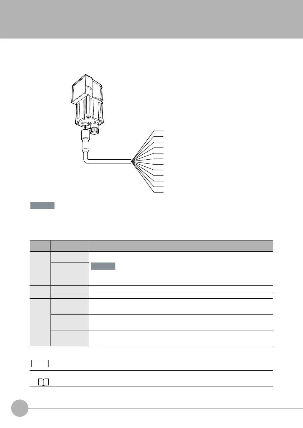
Wiring the Sensor
Connect the I/O Cable to the I/O Cable connector located at the bottom of the Sensor.
• Cut off lines that are not required so that they do not come into contact the other signal lines.
• Do not allow the load current to exceed 50 mA. The output circuit may be damaged if the load current exceeds 50
mA.
Classifi-
cation
Signal Application
Power
supply
Power supply
(24 V)
These terminals are for the external power supply (24 V).
Wire the power supply separately from other devices. If the wiring for other devices is placed
together or in the same duct as the wiring for the Vision Sensor, the influences of electromagnetic
induction may cause the Sensor to malfunction or may damage it.
GND
Inputs TRIG This terminal is the trigger signal input.
IN0 to IN5 These are the command input terminals.
Outputs OUT0 (OR) By default, this is the OR output signal (overall judgement).
The assignment can be changed to RUN, READY, an individual judgement signal from OR0 to
OR31, the STGOUT (strobe trigger output), or an expression judgement from 0 to 31.
OUT1 (BUSY) By default, this is the BUSY output signal.
The assignment can be changed to RUN, READY, an individual judgement signal from OR0 to
OR31, the STGOUT (strobe trigger output), or an expression judgement from 0 to 31.
OUT2 (ERROR) By default, this is the ERROR output signal.
The assignment can be changed to RUN, READY, an individual judgement signal from OR0 to
OR31, the STGOUT (strobe trigger output), or an expression judgement from 0 to 31.
The assignments of I/O signals can be changed.
Section 8 Controlling Operation and Outputting Data with a Parallel Connection: p. 233
GND
OUT0 (OR)
OUT1 (BUSY)
OUT2 (ERROR)
IN0
TRIG
IN1
IN2
IN3
IN4
IN5
Yellow
Purple
White
Red
Green
FQ-WD0@@
I/O Cable
Gray
Pink
Light blue
Orange
Black
Blue
Power supply
Brown
FQ2-S
@@@@@@
(Sensors with Built-in Lighting
or Sensors with C-mounts)
Important
Note

 Loading...


