PLC Link Connections
FQ2 User’s Manual
327
Connecting through Ethernet
9
Setting Up PLC Link Communications
Setting Network Settings in the Sensor
This section describes how to set the IP address and other network settings in the Vision Sensor. Refer to the
following section for details.
2-5 Setting Up Ethernet: p. 53
• Changes to settings are not applied until the Vision Sensor is restarted. Therefore, save the settings and then
restart the Vision Sensor.
5-5 Saving Data to the Sensor p. 178
Restarting the Sensor p. 229
• The port number on the FQ2 Vision Sensor is always 9877.
Initial Settings for PLC Link Communications
You must set the IP address of the PLC to connect to, assign the Command Area, Response Area, and Output
Area, and make other settings to perform PLC Link communications.
(Setup Mode) − [Sensor settings] − [Data output] − [Link data output]
MELSEC-QnAS --- --- Q2ASCPU,
Q2ASCPU-S1,
Q2ASHCPU,
Q2ASHCPU-S1
--- A1SJ71QE71N3-T
1 Press [Communication type].
2 Press [PLC link (SYSMAC)] or [PLC link (MELSEC)]
depending on the PLC that is connected.
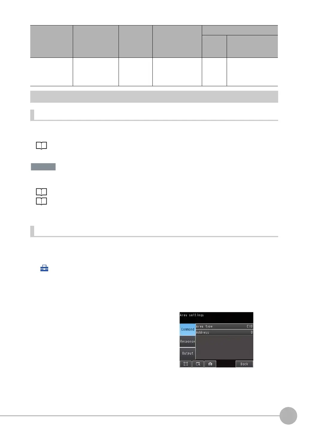
3 Press [Area settings].
Here, you specify the addresses in the I/O memory of
the PLC that are to be allocated as the communica-
tions areas for PLC Link communications.
Press [Command], [Response], and [Output] and set
the memory area ([Area type]) and first word ([Ad-
dress]) in the I/O memory of the PLC to allocate to
each of these communications areas. When you are
finished, press [Back].
Series Model name CPU name CPU Interface
Built-in
port in
CPU Unit
Ethernet Unit

 Loading...


