Controlling Operation and Outputting Data with a Parallel Interface Sensor Data Unit
FQ2 User’s Manual
273
8
Controlling Operation and Outputting Data
with a Parallel Connection
Input Signals to Change the Scene
Clearing Measurement Values
This command clears the measurement values.
Parameters
Timing Chart
Output Signals
Input Signals
Signal Function
IN0 to IN4 These signals specify the scene number (0 to 31).
IN5 Turn ON.
IN6 Turn OFF.
IN7 This signal functions as the execution trigger. Set the IN0 to IN6 signals, wait for at least 5 ms, and then turn ON the IN7
signal. The BUSY signal will be ON while the command is being executed.
Execution Command Input example
IN7 IN6 IN5 IN4 IN3 IN2 IN1 IN0
1 1000000 11000000
Signal Function
RUN This signal is ON while the Sensor is in Run Mode. It will be OFF in Setup Mode.
BUSY This signal does not change while clearing measurement values.
ACK When the command has been completed normally, this signal is turned ON for the time that is set for the ACK output time.
Signal Function
IN0 to IN5 Turn OFF.
IN6 Turn ON.
IN7 This signal is the trigger for clearing measurement values. Set the IN0 to IN6 signals, wait for at least 5 ms, and then turn
ON the IN7 signal.
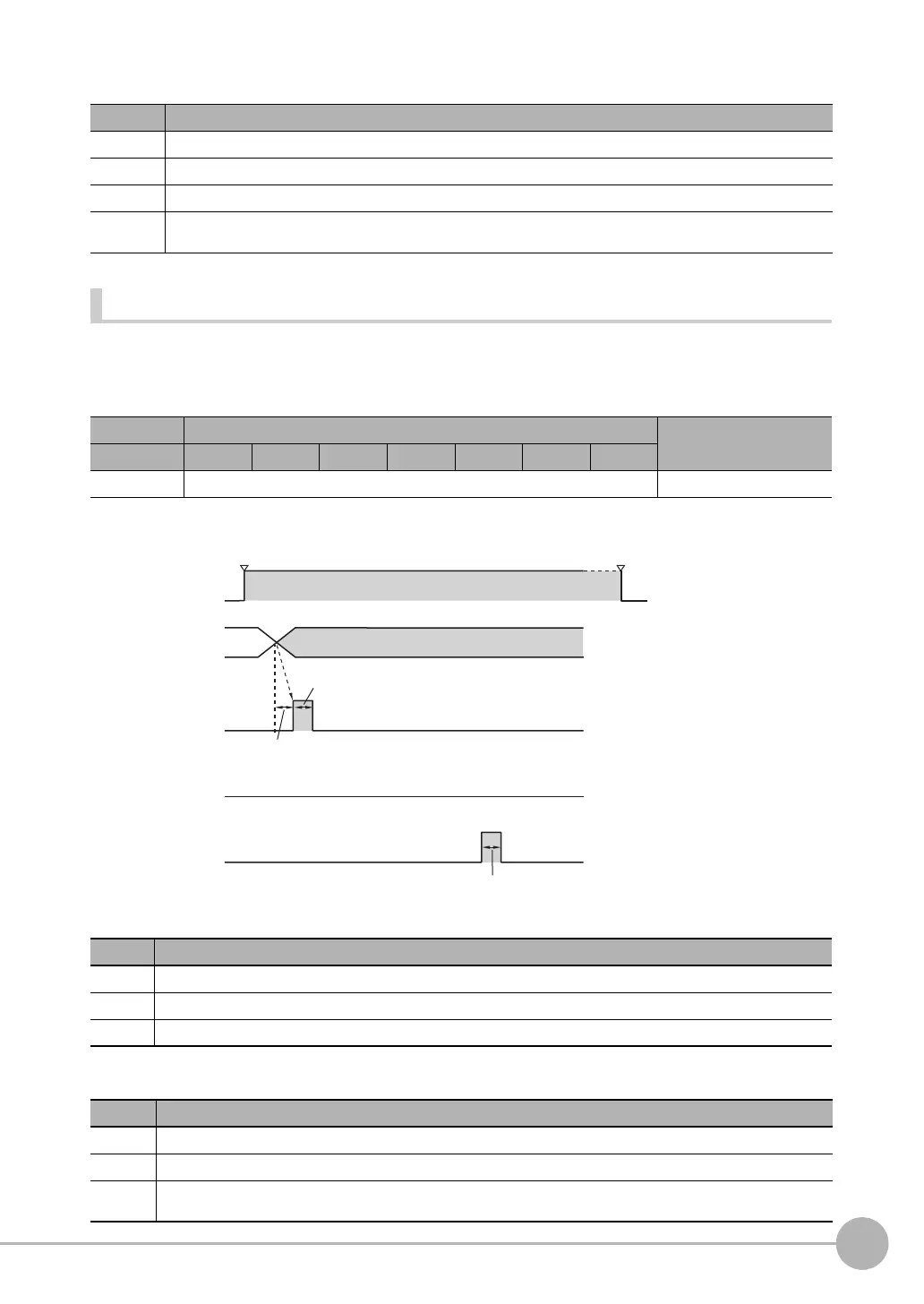
0
IN7 signal
OFF
ON
OFF
ON
RUN signal
OFF
ON
IN0 to IN6
signals
Run Mode entered. Setup Mode entered.
BUSY signal
11000000
Allow 5 ms min. and then turn ON IN7.
ON for 1 ms min.
ACK signal
OFF
ON
ACK output time

 Loading...


