PLC Link Connections
FQ2 User’s Manual
325
Connecting through Ethernet
9
You must specify in advance the data to output after measurements. You must also specify in advance the
Output Area in I/O memory to store the data in the PLC. After a single measurement or continuous
measurements, the data is automatically stored in the Output Area of the PLC via Ethernet.
For PLC Link communications, the following three communications areas are set in the PLC to perform
communications.
You can set the area and address settings in the communications specifications of the Vision Sensor to assign
the above three communications areas in the I/O memory of the PLC.
• An FQ2 Sensor operates as a TCP server. Therefore, the TCP connection must be made from the PLC. Refer to the
manual for the PLC for TCP connection methods.
• The port number on the FQ2 Vision Sensor is always 9877.
Command/response
communications
1. Command area
This is the area to which you write control commands for the
Vision Sensor to execute.
2. Response area
This is the area to which the Vision Sensor writes the results of
control commands executed from the Command Area.
Data output after mea-
surements
3. Output area
This is the area to which the Vision Sensor writes output data for
measurements after an inspection is performed.
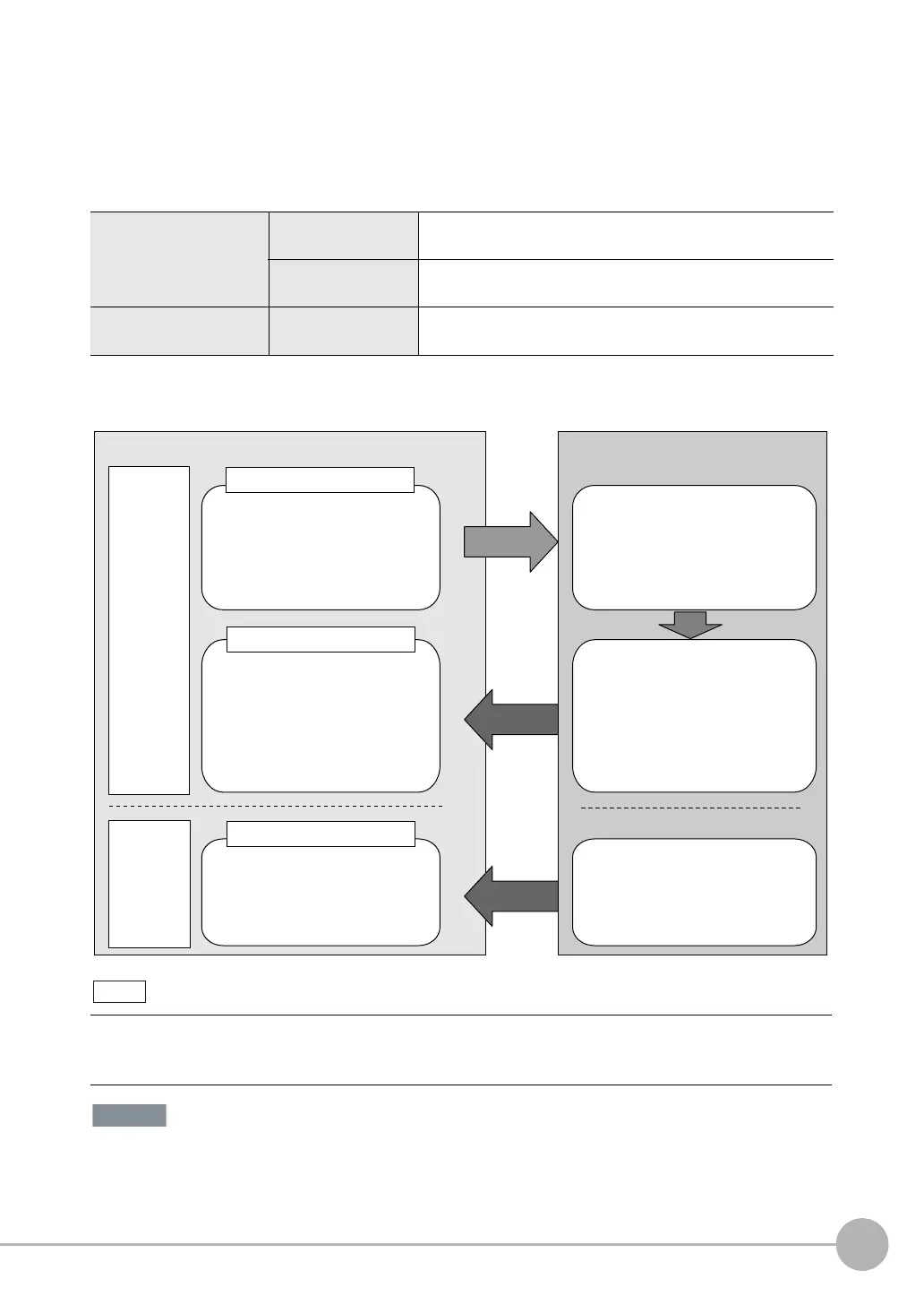
A PLC Link uses three link areas to perform communications: the Command Area, Response Area, and
Output Area. A PLC Link is not the same as the Serial PLC Link protocol used to connect PLCs together with
serial communications.
Command area
The following control commands are
written to the Vision Sensor.
●
Control signals
●
Command code
●
Command parameters
Response area
The execution results from the
Vision Sensor are written here.
PLC (master)
Output area
Output data from the Vision Sensor
is written here.
Vision Sensor (slave)
Command
Response
Measurement results are written to
the Response Area of the PLC.
●
Vision Status Flags
●
Command code
●
Response code
●
Response data
●
Output data 0 to 31
Execution
After measurements
Measurement results are written to the
Output Area.
Command/
response
communi-
cations
The control commands written to the
Command Area are executed.
Data output
after
measure-
ments

 Loading...


