First data output
*
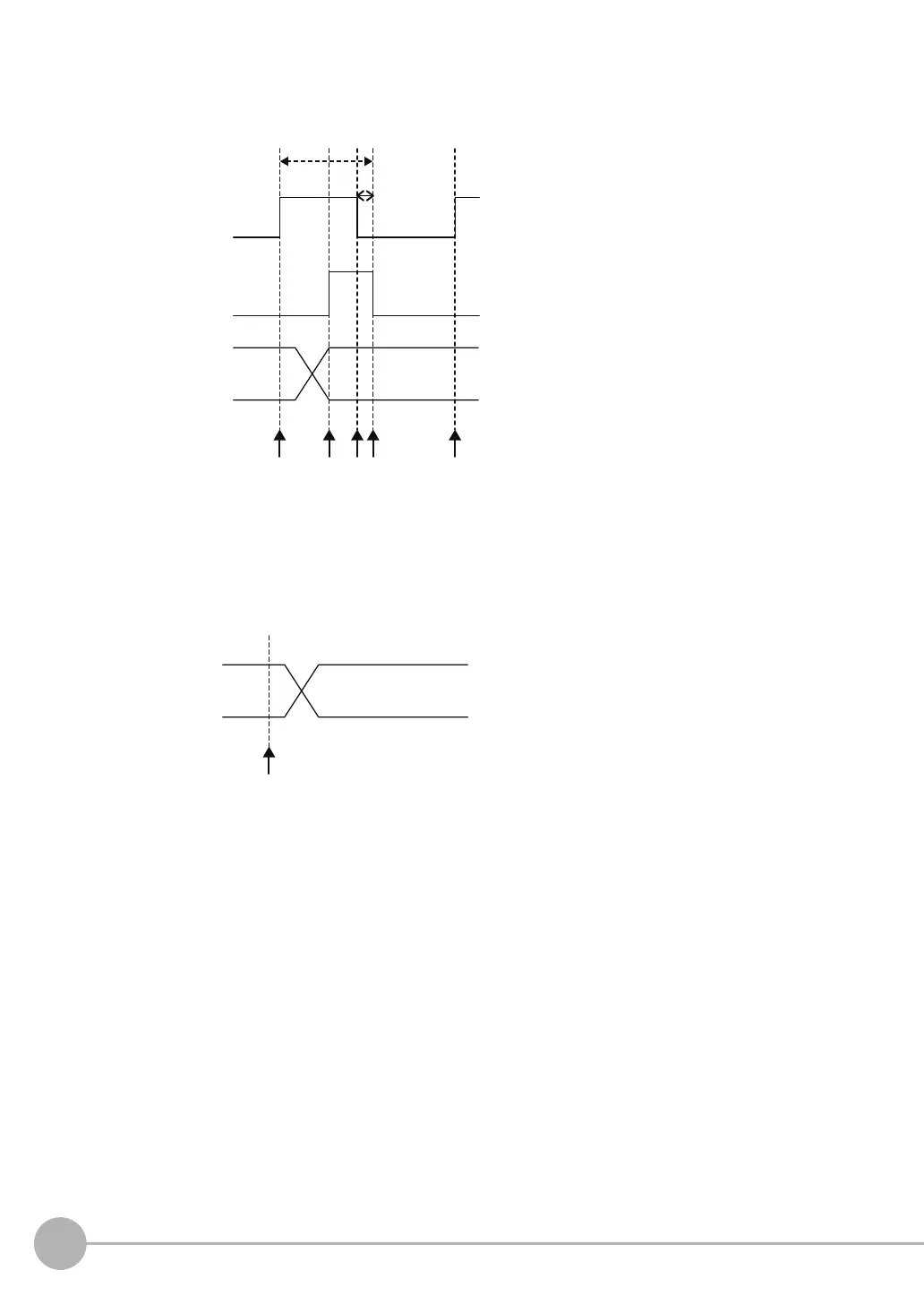
(1) (2) (4) (5)(3)
Output data 0 to
255 (DATA0 to
DATA255)
1. When the PLC is ready to receive
output data, the Data Output Request
Bit (DSA) is turned ON from the PLC
and a request is made to the Vision
Sensor to output the data.
2. The Vision Sensor outputs the data.
After the data is output, the Data
Output Completed (GATE) signal turns
ON.
3. The PLC confirms that the Data
Output Completed (GATE) signal has
turned ON, loads the data, and turns
OFF the Data Output Request Bit
(DSA) signal.
4. When the Vision Sensor detects that
the Data Output Request (DSA)
signal is OFF, it automatically turns
OFF the Data Output Completed
(GATE) signal.
* If the Data Output Request Bit (DSA)
signal is not turned OFF within the
time that is set for the retry interval in
the PLC Link settings, the Data Output
Completed (GATE) signal is forced
OFF and data output is completed.
5. The Data Output Request Bit (DSA)
signal is turned ON from the PLC
and a request is made to output the
following data.
Data Output
Request Bit (DSA)
signal
Data Output
Completed
(GATE) signal
ON
OFF
ON
OFF
ON
OFF
(1)
ON
OFF
Output data 0 to
255 (DATA0 to
DATA255)
1. Data is output automatically when the
Vision Sensor completes a measurement.
* The PLC turns ON the Control
Command Completed (FLG) signal and
then gets the output data.

 Loading...


