EasyManua.ls Logo

Omron fq2 User Manual

Omron fq2
516 pages
To Next Page IconTo Next Page
To Previous Page IconTo Previous Page
Page #358 background imageLoading...
Page #358 background image
Controlling Operation and Outputting Data with TCP No-protocol Communications
356
FQ2 User’s Manual
• When Output Format Is ASCII
Set the parameters for integer digits, decimal digits, negative numbers, 0 suppression, the field separator,
and the record separator.
• Output Format
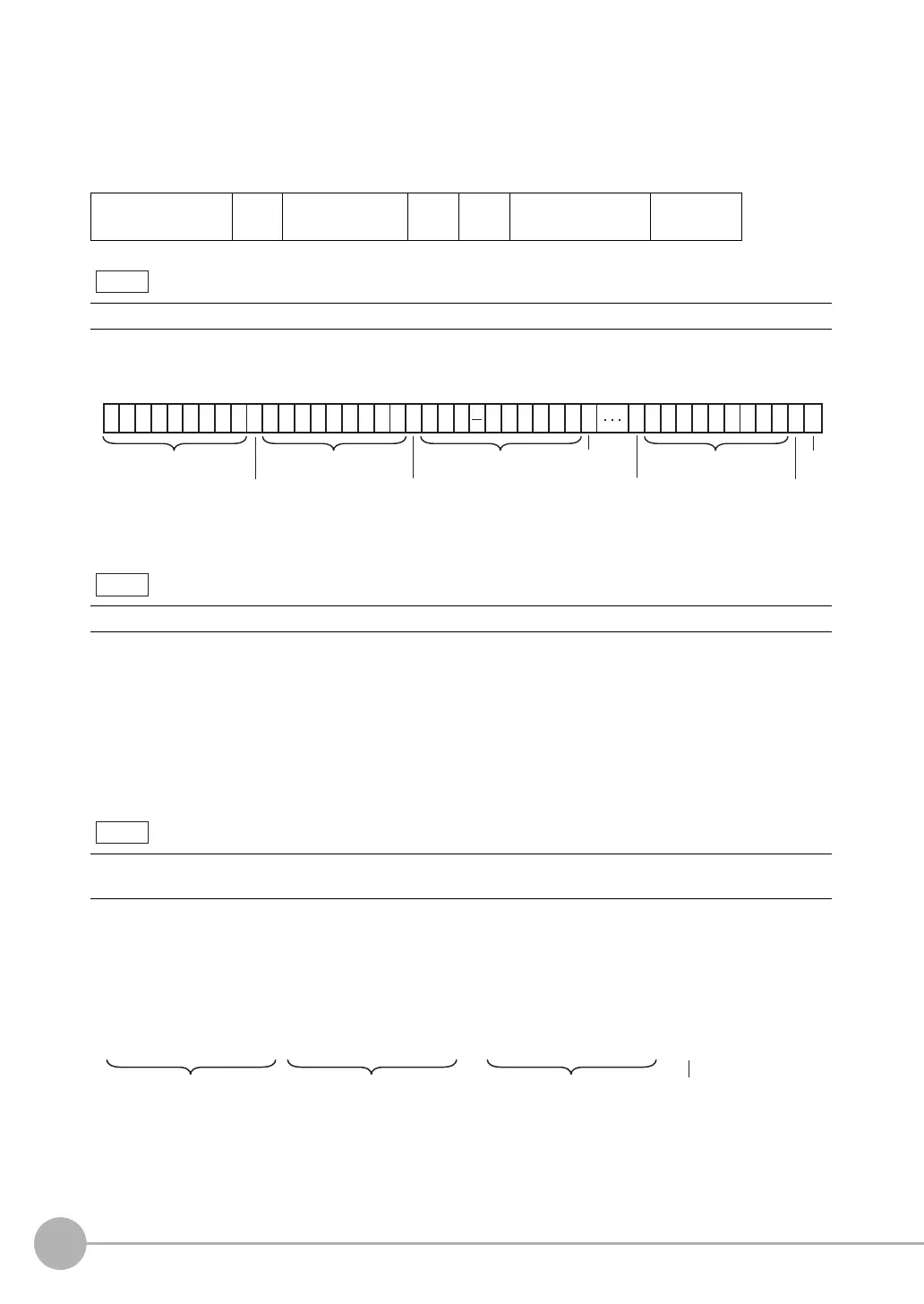
Example: Integer digits: 5, decimal digits: 3, negative number expression: −, zero suppressed: none, field
separator: comma, record separator: CR
*1 Because the record separator is set to CR, only one record is output for each measurement. A blank line (CR:
delimiter) will therefore be entered after the record separator. If you do not want a blank line, set the record sepa-
rator to None.
The following range of values can be output.
−999,999,999.9999 ≤ Measured value ≤ 999,999,999.9999
If the measured value is lower than −999,999,999.9999, then −999,999,999.9999 is output.
If the measured value is higher than 999,999,999.9999, then 999,999,999.9999 is output.
The following values are output if JG (Judge) is set.
OK: 0
NG: −1
• When Output Format Is Binary
Set the numerical expression.
Select either fixed decimal or floating-point decimal.
• Output Format
The measurement data multiplied by 1,000 is output continuously at 4 bytes per data. Negative numbers are
output as two’s complements.
Measured value of
data 0
,
Measured value of
data 1
,· · ·
Measured value of
data 7
CR
The data output method, digits, and data separators can be changed as needed.
The field separator is not output unless the data continues.
Data that is output after measurement is output until the last data even after the measurement is finished. Data out-
put is not interrupted midway.
Note
1
Measured value of data 0
1221123345 567 6 6 65 65
CR
998 7778.. . .,, ,,
Measured value
of data 1
Measured
value of data 7
Measured
value of data 2
Field separator Record separator
*1
Delimiter
Field separator
Field separator
Field separator
CR
Note
Note
4 bytes 4 bytes 4 bytes
<Measured value of data 0 × 1,000><Measured value of data 1 × 1,000> <Measured value of data 7 × 1,000>
· · ·
CR
Delimiter

Table of Contents

Question and Answer IconNeed help?

Do you have a question about the Omron fq2 and is the answer not in the manual?

Omron fq2 Specifications

General IconGeneral
BrandOmron
Modelfq2
CategoryDigital Camera
LanguageEnglish

Summary

2. Installation and Connections

2-3 Installation

Provides step-by-step instructions for installing the FQ2 sensors, including mounting procedures.

2-4 Wiring

Details the wiring connections for the sensor, data units, and power supply, including I/O signal diagrams.

2-5 Setting Up Ethernet

Guides on configuring network settings, including IP addresses for sensors and the Touch Finder.

3. Taking Images

3-2 Setting Conditions for Taking Images

Details how to set image capture conditions, including camera setup, timing, and image adjustment.

3-3 Adjusting Image Quality

Covers adjusting focus, brightness, and color balance to optimize image quality for inspections.

3-5 Adjusting the Images That Were Taken

Describes image adjustment techniques like filtering and position offset compensation for easier measurement.

4. Setting Up Inspections

4-2 Setup Procedure for Inspection Items

Outlines the basic steps for setting up inspection items, including teaching and parameter adjustment.

4-3 Configuring Inspection Items

Details how to add new inspection items, modify existing ones, and delete them.

4-4 Inspecting with the Search Inspection Item

Explains how to use the Search inspection item for shape or presence detection by matching image patterns.

4-5 Inspecting with the Shape Search II Inspection Item

Describes the Shape Search II inspection item for high-precision detection focusing on outline information.

4-6 Inspecting with the Sensitive Search Inspection Item

Covers the Sensitive Search inspection item for detailed matching by dividing the model into smaller areas.

4-7 Inspecting with the Edge Position Inspection Item

Details how to inspect positions by detecting edges and measuring their locations.

4-8 Inspecting with the Edge Width Inspection Item

Explains how to measure dimensions by detecting edges and calculating the distance between them.

4-9 Inspecting with the Edge Pitch Inspection Item

Describes how to detect edges and output object width and pitch.

4-10 Inspecting with Color Data Inspection Item

Covers inspections for foreign matter or presence based on color within a measurement region.

4-11 Inspecting with the Area Inspection Item

Explains how to measure sizes by calculating the amount of color within a measurement region.

5. Testing and Saving Settings

6. Operation

8. Controlling Operation and Outputting Data with a Parallel Connection

9. Connecting through Ethernet

10. Connecting with RS-232C

11. Troubleshooting

Related product manuals