n
H3-13: Analog Input Filter Time Constant
Parameter
H3-13 sets the time constant for a first order filter that will be applied to analog input A1 and also to the reference
value from potentiometer option (AI-V3/J).
No. Name Setting Range Default
H3-13 Analog Input Filter Time Constant 0.00 to 2.00 s 0.03 s
An analog input filter can be used to prevent erratic drive control when a “noisy” analog reference is used. The drive
operation
becomes more stable the longer the time programmed, but it becomes less responsive to rapidly changing analog
signals.
u
H4: Multi-Function Analog Output Terminal AM
These parameters assign a function to analog output terminal AM for monitoring a specific aspect of drive performance.
n
H4-01: Multi-Function Analog Terminal AM Monitor Selection
Sets the desired drive monitor parameter U- to output as an analog value via terminal AM. Refer to U:
Monitors
on page 181 for a list of all monitors. The “Analog Output Level” columns indicates if a monitor can be applied
for analog output.
Example: Enter “103” for U1-03.
No. Name Setting Range Default
H4-01 Multi-Function Analog Terminal AM Monitor Selection 000 to 999 102
A setting of 031 or 000 applies no drive monitor to the analog output. With this setting the terminal AM output level can
be set by a PLC via a MEMOBUS/Modbus communications interface (through mode).
n
H4-02/H4-03: Multi-Function Analog Output Terminal AM Gain/Bias
Parameter
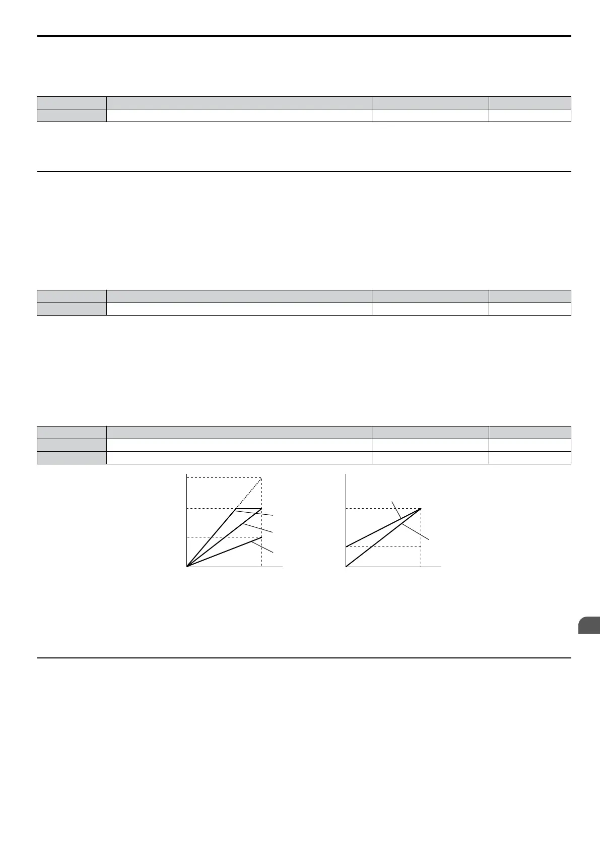
H4-02 sets the output voltage that is equal to 100% of the monitor value. Parameter H4-03 sets the output voltage
equal to 0% of the monitor value.
Both values are set as a percentage of 10 V. The minimum output voltage for terminal AM is 0 V, the maximum is 10
Vdc. Figure 5.32 illustrates the function of the gain and bias settings.
No. Name Setting Range Default
H4-02 Multi-Function Analog Output Terminal AM Gain -999.9 to 999.9% 100.0%
H4-03 Multi-Function Analog Output Terminal AM Bias -999.9 to 999.9% 0.0%
0 V
3 V
10 V
Bias 30%
Gain 100%
Bias 0%
Gain 100%
100%
Monitor value
0%
Gain 50%
Bias 0%
Terminal AM
output
voltage
0 V
5 V
10 V
Gain 150%
Bias 0%
Gain 100%
Bias 0%
100%
Monitor value
0%
Terminal AM
output
voltage
Figure 5.32 Analog Output Gain/Bias Setting
When viewing the settings for H4-02, terminal AM will output a voltage that is equal to 100% of the monitor value
(considering
the present setting). When viewing the settings for H4-03, terminal AM will output a voltage that is equal to
0% of the monitor value.
u
H5: MEMOBUS/Modbus Serial Communication
Through the drives optional RS-422/485 interface, serial communication can be performed with programmable logic
controllers (PLCs) or similar devices using the MEMOBUS/Modbus protocol.
The H5- parameters are used to set up the drive for MEMOBUS/Modbus Communications. Refer to MEMOBUS/
Modbus Serial Communication on page 191 for detailed descriptions of the H5- parameters.
5.6 H: Terminal Functions
SIEP C710606 33A OYMC AC Drive – J1000 User Manual
101
5
Parameter Details
 Loading...


