3.3 Main Circuit Connection Diagram
Refer to diagrams in this section for the Main Circuit wiring connections. Connections may vary based on drive capacity.
The main circuit DC power supply powers the control circuit.
NOTICE: Do not use the negative DC bus terminal “-” as a ground terminal. This terminal is at high voltage DC potential. Improper
wiring connections could result in damage to the drive.
u
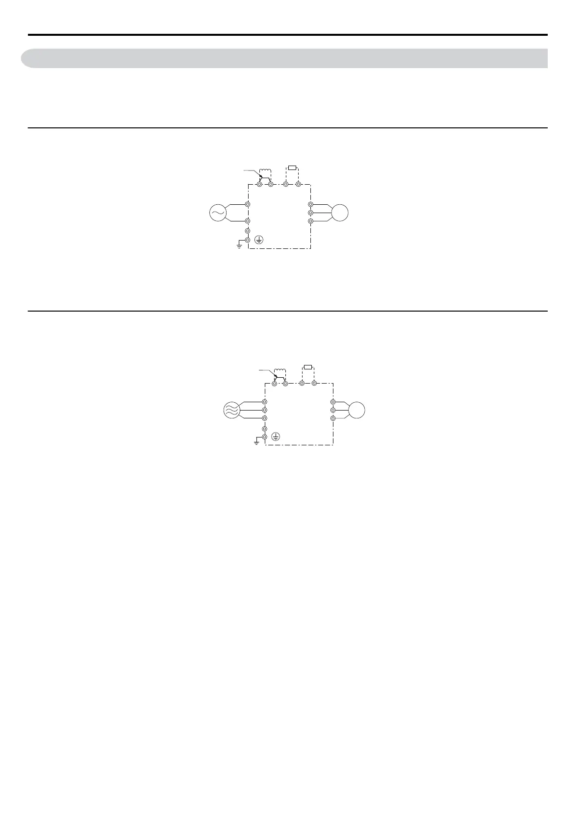
Single-Phase 200 V Class (JZAB0P1 ~ B1P5)
Drive
Jumper
Single-phase
200 Vac
Motor
DC reactor
(option)
Braking Resistor
Unit (option)
R/L1
S/L2
+1
+2
–
B1 B2
U/T1
V/T2
W/T3
Figure 3.3 Connecting Single-Phase Main Circuit Terminals
NOTICE: Do not connect T/L3 terminal when using single-phase power supply input. Incorrect wiring may damage the drive.
u
Three-Phase 200 V Class (JZA20P1 ~ 24P0); Three-Phase 400 V Class (JZA40P2 ~
44P0)
—
Drive
Motor
Three phase 200 Vac
(400 Vac)
Braking
Resistor Unit
(option)
R/L1
S/L2
T/L3
U/T1
V/T2
W/T3
B1 B2
Jumper
DC reactor
(option)
+1
+2
Figure 3.4 Connecting Three-Phase Main Circuit Terminals
3.3 Main Circuit Connection Diagram
34
SIEP C710606 33A OYMC AC Drive – J1000 User Manual
 Loading...


