C.10 MEMOBUS/Modbus Data Table
Table below lists all MEMOBUS/Modbus data. There are three types of data: command data, monitor data, and broadcast
data.
u
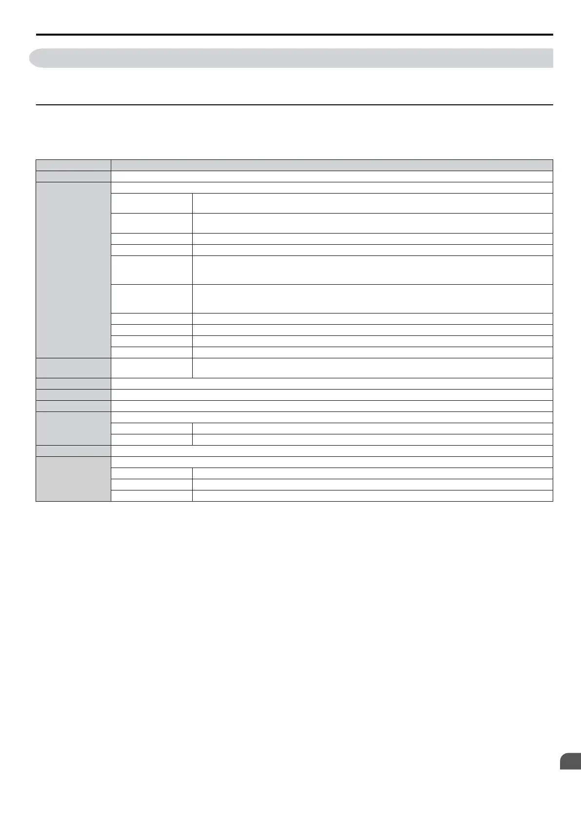
Command Data
It is possible to both read and write command data.
Note: Bits that are not used should be set to 0. Refrain from writing to reserved registers.
Register No. Contents
0000H Reserved
0001H
Operation Signals and Multi-function Inputs
bit 0
H5-12 = 0: Forward Run Command (0 = Stop, 1 = Forward Run)
H5-12 = 1: Run Command (0 = Stop, 1 = Run)
bit 1
H5-12 = 0: Reverse Run Command (0 = Stop, 1 = Reverse Run)
H5-12 = 1: Forward/Reverse (0 = Forward, 1 = Reverse)
bit 2 External Fault (EF0)
bit 3 Fault Reset
bit 4
Multi-Function Input 1
Function is ComRef when H1-01 = 40 (Forward/Stop). Refer to d: Reference Settings on page 82 for
ComRef explanations.
bit 5
Multi-Function Input 2
Function is ComCtrl when H1-02 = 41 (Reverse/Stop). Refer to d: Reference Settings on page 82 for
ComCtrl explanations.
bit 6 Multi-Function Input 3
bit 7 Multi-Function Input 4
bit 8 Multi-Function Input 5
bit 9 to F Reserved
0002H Frequency Reference
Units are determined by parameter H5-13 (MEMOBUS frequency reference and frequency monitor
unit).
0003H-0006H Reserved
0007H Analog Output Terminal AM Setting (10 V / 4000 H)
0008H Reserved
0009H
Settings for Multi-Function Digital Outputs
bit 0 Contact Output (terminal MA/MB-MC)
bit 1 to F Reserved
000AH-000EH Reserved
000FH
Control Selection Setting
bit 0 to B Reserved
bit C Enable Terminal S5 Input for Broadcast Data
bit D to F Reserved
C.10 MEMOBUS/Modbus Data Table
SIEP C710606 33A OYMC AC Drive – J1000 User Manual
199
C
MEMOBUS/Modbus
Communications
 Loading...


