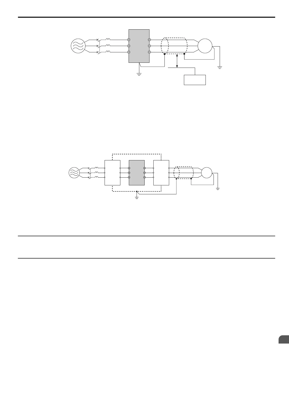
B
A
C
F
G
D
E
R/L1
MCCB
S/L2
T/L3
U/T1
V/T2
W/T3
A – Power supply
B – Drive
C – Shielded motor cable
D – Motor
E – Separate at least 30 cm
F – Controller
G – Signal line
Figure 8.8 Preventing Induced Noise
Reducing Radiated/Radio Frequency Noise
The drive, input lines, and output lines generate radio frequency noise. Use noise filters on input and output sides and
install the drive in a metal enclosure panel to reduce radio frequency noise.
Note: The cable running between the drive and motor should be as short as possible.
C ED
B
F
A
R/L1
MCCB
S/L2
T/L3
U/T1
V/T2
W/T3
G
A – Metal enclosure
B – Power supply
C – Noise filter
D – Drive
E – Noise filter
F – Shielded motor cable
G – Motor
Figure 8.9 Reducing Radio Frequency Noise
u
Installing Fuses on the Input Side
Always install input fuses. Refer to Standards Compliance on page 209 for details on input fuse selection.
u
Installing a Motor Thermal Overload (oL) Relay on the Drive Output
Motor thermal overload relays protect the motor by disconnecting power lines to the motor due to a motor overload
condition.
Install a motor thermal overload relay between the drive and motor:
•
When operating multiple motors on a single AC drive.
• When using a power line bypass to operate the motor directly from the power line.
It is not necessary to install a motor thermal overload relay when operating a single motor from a single AC drive. The
AC drive has UL recognized electronic motor overload protection built into the drive software.
Note: Disable the motor protection function (L1-0 1 = “0”) when using an external motor thermal overload relay. The relay should shut off main
power on the input side of the main circuit when triggered.
n
General Precautions when Using Thermal Overload Relays
The following application precautions should be considered when using motor thermal overload relays on the output of
AC drives in order to prevent nuisance trips or overheat of the motor at low speeds:
• Low speed motor operation
• Use of multiple motors on a single AC drive
• Motor cable length
• Nuisance tripping resulting from high AC drive carrier frequency
8.4 Installing Peripheral Devices
SIEP C710606 33A OYMC AC Drive – J1000 User Manual
155
8
Peripheral Devices &
Options
 Loading...


