Setting 67: Communication Test Mode
If
a RS-422/485 communications options is attached to the drive, this function can be used to perform a self-diagnosis of
the communication interface. The drive transmits data and then confirms the communications are received normally. Refer
to Self-Diagnostics on page 207 for details on how to use this function.
u
H2: Multi-Function Output
n
H2-01: Terminal MA/MB/MC Function Selection
The
drive has a multi-function output terminal. Set parameter H2-01 between 0 and 13D to assign functions to this terminal.
Default values are listed in the following table.
No. Parameter Name Setting Range Default
H2-01 Terminal MA, MB and MC Function Selection (relay) 0 to 13D E: Fault
Note: If not using an input terminal or if using it in the through-mode, be sure to set that terminal to “F”.
Table 5.16 Multi-Function Output Terminal Settings
Setting Function Page Setting Function Page
0 During Run 95 E Fault 97
1 Zero Speed 95 F Not used/Through Mode 97
2 Speed Agree 96 10 Alarm 97
4 Frequency Detection 1 96 17 Torque Detection 1 (N.C.) 97
5 Frequency Detection 2 96 1A During Reverse Operation 98
6 Drive Ready 97 1E Restart Enabled 98
7 DC Bus Undervoltage 97 3C LOCAL/REMOTE Status 98
8 During Baseblock (N.O.) 97 3D During Speed Search 98
B Torque Detection 1 (N.O.) 97 100 to 13D
H2 Parameter Functions Reversed Output
Switching of 0 to 92
98
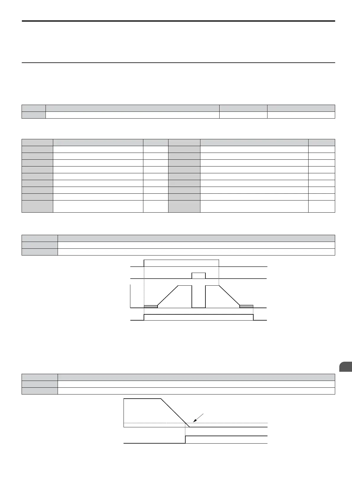
Setting 0: During Run
Output closes when the drive is outputting a voltage.
Status Description
Open Drive is stopped.
Closed A Run command is input or the drive is during deceleration or during DC injection.
ON
ON
OFF
OFF
ONOFF
Run command
Baseblock
command
Output
frequency
During Run
Figure 5.20 During Run Time Chart
Setting 1: Zero Speed
Terminal closes whenever the output frequency falls below the minimum output frequency set to E1-09.
Status Description
Open Output frequency is above the minimum output frequency set to E1-09
Closed Output frequency is less than the minimum output frequency set to E1-09
OFF
Output frequency
or
motor speed
Zero Speed
ON
E1-09 (Max. Output Frequency)
Figure 5.21 Zero-Speed Time Chart
5.6 H: Terminal Functions
SIEP C710606 33A OYMC AC Drive – J1000 User Manual
95
5
Parameter Details
 Loading...


