No. Name Description Range Def. Mode
Addr.
Hex
Pg.
d3-01 Jump Frequency 1 d3-01 to d3-04 allow programming of three prohibited frequency
reference points for eliminating problems with resonant vibration
of the motor/machine. This feature does not eliminate the selected
frequency values, but accelerates and decelerates the motor through
the prohibited bandwidth.
The parameters must be according to the rule
d3-01 ≥ d3-02 .
0.0 to 400.0
0.0 Hz O 294 84
d3-02 Jump Frequency 2 0.0 Hz O 295 84
d3-04
Jump Frequency
Width
This parameter sets the dead-band width around each selected
prohibited frequency reference point. The bandwidth becomes the
designated Jump frequency, plus or minus d3-04.
0.0 to 20.0 1.0 Hz O 297 84
d4: Frequency Reference Hold
Use d4 parameters to configure the drive frequency reference hold function.
d4-01
Frequency
Reference Hold
Function Selection
Determines if the frequency reference or frequency reference bias
is saved when the Run command is removed or the power goes off.
0: Disabled
1: Enabled
This parameter is effective when the multi-function inputs “Accel/
Decel Ramp Hold” or “Up/Down” commands are selected (H1-
= A or 10/11).
0, 1 0 O 298 84
<19> Range upper limit is dependent on parameters E1-04, Maximum Output Frequency, and d2-01, Frequency Reference Upper Limit.
<22>
Parameter can be changed during run.
u
E: Motor Parameters
E parameters set V/f characteristics and motor-related data.
No. Name Description Range Def. Mode
Addr.
Hex
Pg.
E1: V/f Pattern Characteristics
Use E1 parameters to set V/f characteristics for the motor.
E1-01
<24>
Input Voltage
Setting
This parameter must be set to the power supply voltage.
WARNING! Drive input voltage (not motor voltage) must be set
in
E1-01 for the protective features of the drive to function properly.
failure to do so may result in equipment damage and/or death or
personal injury.
155 to 255 200 S 300 86
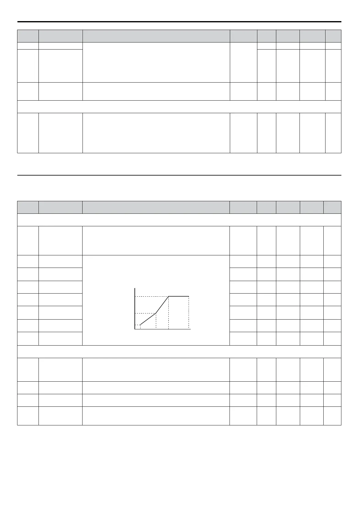
E1-04
Max Output
Frequency
To set linear V/f characteristics, set the same values for E1-07 and
E1-09.
In this case, the setting for E1-08 will be disregarded. Ensure
that the four frequencies are set according to these rules:
E1-04 ≥ E1-06> E1-07 ≥ E1-09
E1-05
E1-08
E1-10
E1-09 E1-07 E1-06 E1-04
VACrms Out (V)
Frequency (Hz)
40.0 to
400.0
50 Hz S 303 86
E1-05
<24>
Max Output
Voltage
0.0 to 255.0 200 V S 304 86
E1-06 Base Frequency
0.0 to
E1-04
50 Hz O 305 86
E1-07
Mid Output
Frequency
0.0 to
E1-04
2.5 Hz O 306 86
E1-08
<24>
Mid Output
Frequency
Voltage
0.0 to 255.0 16.0 V O 307 86
E1-09
Minimum Output
Freq.
0.0 to
E1-04
1.3 Hz S 308 86
E1-10
<24>
Minimum Output
Freq. Voltage
0.0 to 255.0 12.0 V O 309 86
E2: Motor Parameters
Use E2 parameters to set motor-related data.
E2-01
Motor Rated
Current
Sets the motor nameplate full load current in amperes (A).
10 to 200%
of drive
rated
current
<57>
S 30E 88
E2-02 Motor Rated Slip Sets the motor rated slip in Hertz.
0.00 to
20.00
<57>
O 30F 88
E2-03
Motor No-Load
Current
Sets the magnetizing current of the motor in Ampere.
0 to less
than E2-01
<57>
O 310 88
E2-05
Motor
Line-to-Line
Resistance
Sets the phase-to-phase motor resistance in ohms.
0.000 to
65.000
<37>
<57>
O 312 88
<24> Values shown here are for 200 V class drives. Double the value when using a 400 V class drive.
<37>
Setting range becomes 0.00 to 130.00 for drives 0.2 kW and smaller.
<57> Default setting value is dependent on parameter o2-04, Drive Model Selection and C6-01, Drive Duty Selection.
B.2 Parameter Table
174
SIEP C710606 33A OYMC AC Drive – J1000 User Manual
 Loading...


