The following example is a continuation of the steps beginning on page 59. Here, parameter
C1-01 is accessed using the
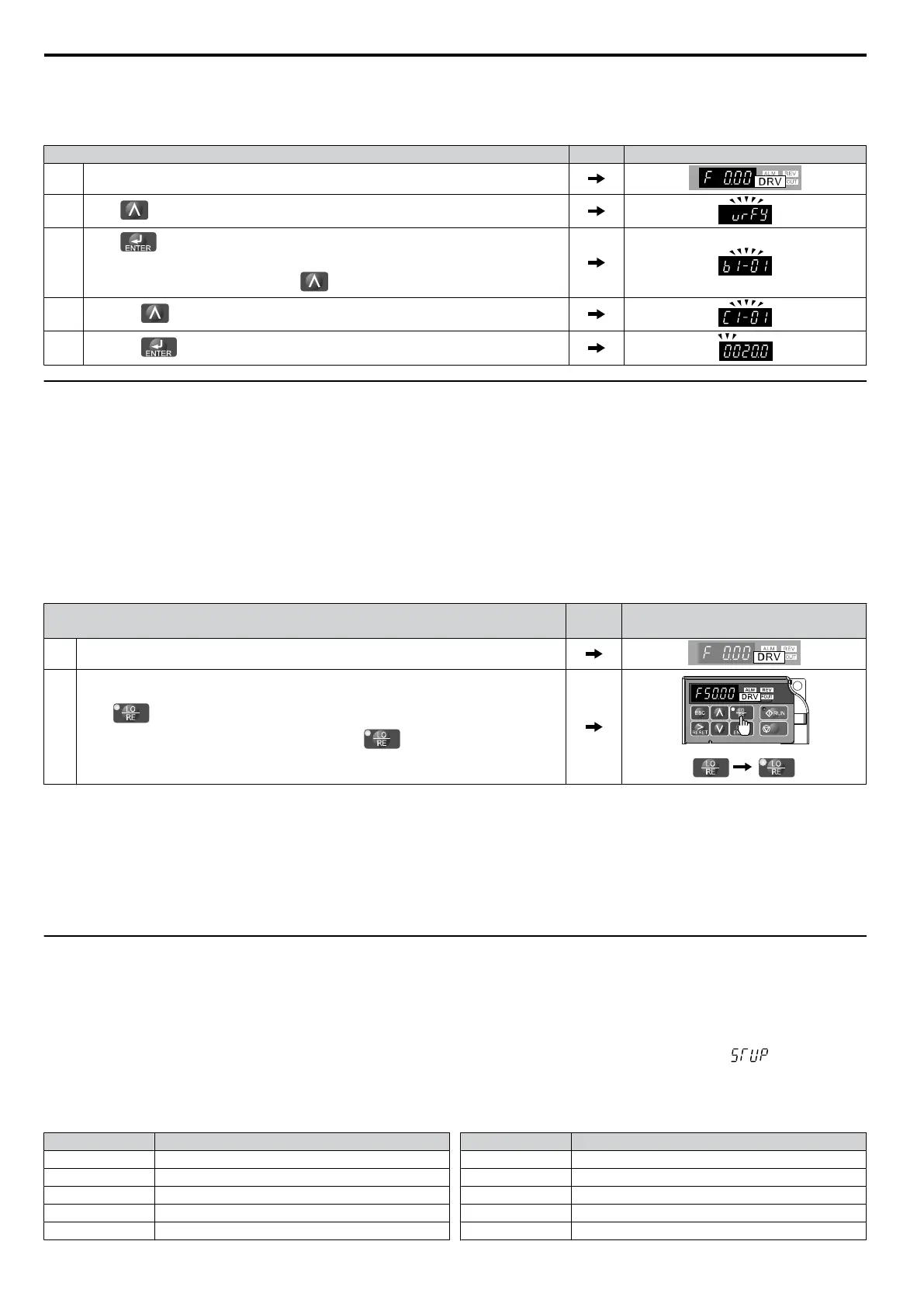
Verify Menu and is changed again to 20.0 s.
To check the list of edited parameters:
Step Display/Result
1. Turn on the power to the drive. The initial display appears.
2.
Press until the display shows the “Verify” representation.
3.
Press to enter the list of parameters that have been edited from their original
default settings.
Scroll through the list by pressing the
key.
4.
Press the key until C1-01 appears.
5.
Press the key to access the setting value. (number farthest to the left flashes)
u
Switching Between LOCAL and REMOTE
Entering the run command using the LED operator is referred to as LOCAL, while entering the run command from an
external device via the control circuit terminals or network option unit is referred to as REMOTE.
WARNING! Sudden
Movement Hazard. The drive may start unexpectedly if the Run command is already applied when switching from
LOCAL mode to REMOTE mode when b1-07 = 1, resulting in death or serious injury. Be sure all personnel are clear of rotating machinery
and electrical connections prior to switching between LOCAL mode and REMOTE mode.
There are two ways to switch between LOCAL and REMOTE.
Note: 1. After selecting LOCAL, the LO/RE light will remain lit.
2. The drive will not allow the user to switch between LOCAL and REMOTE during run.
n
Using the LO/RE Key on the LED Operator
Step Display/Result
1. Turn on the power to the drive. The initial display appears.
2.
Press . The LO/RE light will light up. The drive is now in Local.
To set the drive for REMOTE operation, press the key again.
STOP
n
Using Input Terminals S1 through S5 to Switch between LO/RE
Switch between LOCAL and REMOTE using one of the digital input terminals S1 through S5 (set the corresponding
parameter H1-01 through H1-05 to “1”).
Follow the example below to set the digital input terminals.
Note: 1. For a list of digital input selections, Refer to Parameter List on page 169.
2. Setting a multi-function input terminal to a value of 1 disables the LO/RE key on the LED operator.
u
Parameters Available in the Setup Group
n
Setup Mode (STUP)
Parameters
used for this drive are classified into A to U. To simplify the drive setup, frequently used parameters are selected
and input into Setup Mode.
1.
To set a parameter, the Setup Mode must be displayed first. Press the Up/Down key until is displayed.
2.
Select the parameter and change the setting. Table 4.4 lists parameters available in the Setup group. If the desired
parameter cannot be set in the Setup mode, use the Parameter Setting mode.
Table 4.4 Setup Group Parameters
Parameter Name
b1-01 Frequency Reference Selection
b1-02 Run Command Selection
b1-03 Stop Method Selection
C1-01 Acceleration Time 1
C1-02 Deceleration Time 1
Parameter Name
C6-01 Duty Selection
C6-02 Carrier Frequency Selection
d1-01 Frequency Reference 1
d1-02 Frequency Reference 2
d1-03 Frequency Reference 3
4.3 The Drive and Programming Modes
60
SIEP C710606 33A OYMC AC Drive – J1000 User Manual
 Loading...


