3.8 I/O Connections
u
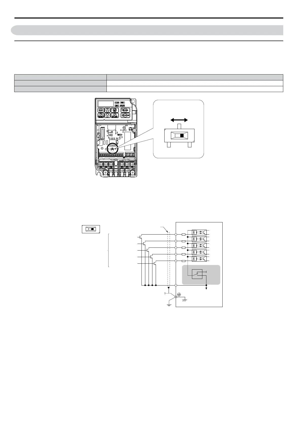
Sinking/Sourcing Mode Switch
Set
the DIP switch S3 on the front of the drive to switch the digital input terminal logic between sinking mode and sourcing
mode; the drive is preset to sinking mode.
Table 3.10 Sinking/Sourcing Mode Setting
Set Value Details
SINK Sinking Mode (0 V common): default setting
SOURCE Sourcing Mode (+24 V common)
SINK
SOURCE
DIP Switch S3
Figure 3.16 DIP Switch S3
n
Transistor Input Signal Using 0 V Common/Sink Mode
When controlling the digital inputs by NPN transistors (0 V common/sinking mode), set the DIP switch S3 to SINK and
use the internal 24 V power supply.
S1
SINK
SOURCE
S2
S3
S3
+24 V
S4
S5
SC
SINK
SOURCE
FWD Run/Stop
REV Run/Stop
External Fault N.O.
Fault Reset
Multi-step Speed 1
Shielded Cable
Multi-funciton input
Figure 3.17 Sinking Mode: Sequence from NPN Transistor (0 V Common)
n
Transistor Input Signal Using +24 V Common/Source Mode
When controlling digital inputs by PNP transistors (+24 V common/sourcing mode), set the DIP switch S3 to SOURCE
and use an external 24 V power supply.
3.8 I/O Connections
44
SIEP C710606 33A OYMC AC Drive – J1000 User Manual
 Loading...


