n
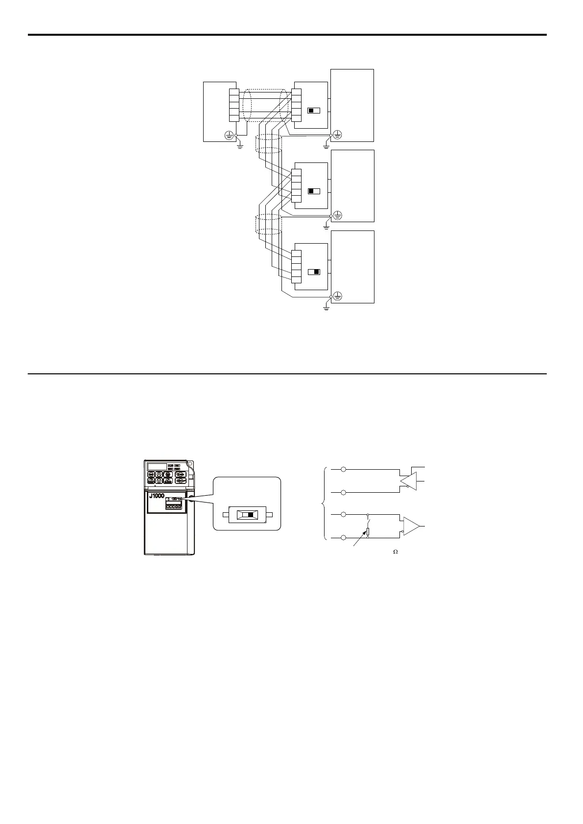
RS-422 Interface
S+
S–
IG
R+
R–
PLC
SI-485/J
OFF
S2
R+
R–
IG
S+
S–
SI-485/J
OFF
S2
R+
R–
IG
S+
S–
SI-485/J
ON
S2
R+
R–
IG
S+
S–
Drive
Drive
Drive
Terminating
Register
Terminating
Register
Terminating
Register
Figure C.4 RS-422 Interface
Note: •
Turn on the DIP switch at the SI-485/J that is located at the end of the network. Turn it off at all other slaves.
• Set H5-07 to “0” when using the RS-485 interface.
u
Network Termination
The two ends of the MEMOBUS/Modbus network line have to be terminated. The Interface for MEMOBUS/Modbus
Communication (SI-485/J) has a built in terminating resistance that can be enabled or disabled using DIP switch S2. If a
drive
is located at the end of a network line, enable the terminating resistance by setting DIP switch S2 to the ON position.
Disable the terminating resistance on all slaves that are not located at the network line end. Figure C.5 llustrates the setting
of DIP switch S2.
R+
R
-
S+
S
-
+
-
RS-422
or
RS-485
DIP
switch
S2
terminal resistance (1/2 W, 110
)
DIP switch S2
(in the ON position)
OFF ON
Figure C.5 Serial Communications Terminal and DIP Switch S2
C.4 Connecting to a Network
190
SIEP C710606 33A OYMC AC Drive – J1000 User Manual
 Loading...


