5.2 b: Application
Application parameters configure the source of the frequency reference, the Run command, DC Injection Braking, and
other application-related settings.
u
b1: Mode of Operation
n
b1-01: Frequency Reference Selection
Use parameter b1-01 to select the frequency reference source for the REMOTE mode.
Note: 1. If a Run command is input to the drive but the frequency reference entered is 0 or below the minimum frequency, the RUN indicator
LED on the digital operator will light and the STOP indicator will flash.
2. Press the LO/RE key to set the drive to LOCAL and use the operator keypad to enter the frequency reference.
No. Parameter Name Setting Range Default
b1-01 Frequency Reference Selection 0 to 3 1
Setting 0: Operator Keypad
Using this setting, the frequency reference can be input by:
•
Switching between the multi-speed references in the d1- parameters.
•
Entering the frequency reference on the operator keypad.
Setting 1: Terminals (Analog Input Terminals)
Using this setting, an analog frequency reference can be entered from terminal A1 using a 0 to 10 Vdc or a 0/4 to 20 mA
signal.
Note: The input signal type must be set up by setting DIP switch S1 and adjusting parameter H3-01. Refer to H3-01: Terminal A1 Signal Level
Selection on page 98.
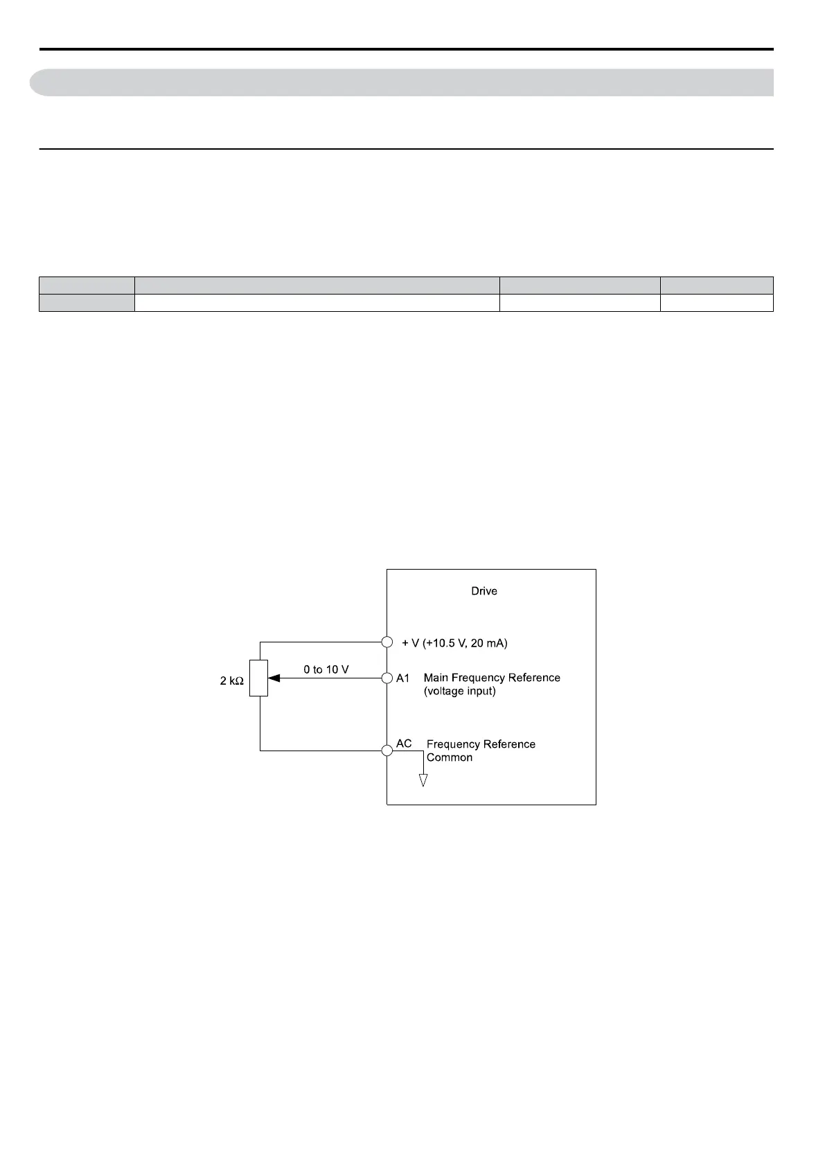
Using a 0 to 10 Vdc Voltage Input Signal:
Use a circuit such as the one shown in Figure 5.1 or an external 0 to 10 Vdc voltage source like a PLC analog output and
set the input level selection for A1 in parameter H3-01 as desired. Refer to H3-01: Terminal A1 Signal Level Selection
on page 98 .
Figure 5.1 Setting the Frequency Reference by Voltage Input
Using a 0/4 to 20 mA Current Input Signal:
Connect input A1 to an external current source such as the one shown in Figure 5.2. Make sure that switch S1 is set to
“I” and set the appropriate signal level by entering 2 (4 to 20 mA) or 3 (0 to 20 mA) into parameter H3-01.
5.2 b: Application
72
SIEP C710606 33A OYMC AC Drive – J1000 User Manual
 Loading...


