No. Display Name Function
12 ALM LED Light
Refer to LED Screen Displays on page 55.
13 REV LED Light
14 DRV LED Light
15 FOUT LED Light
u
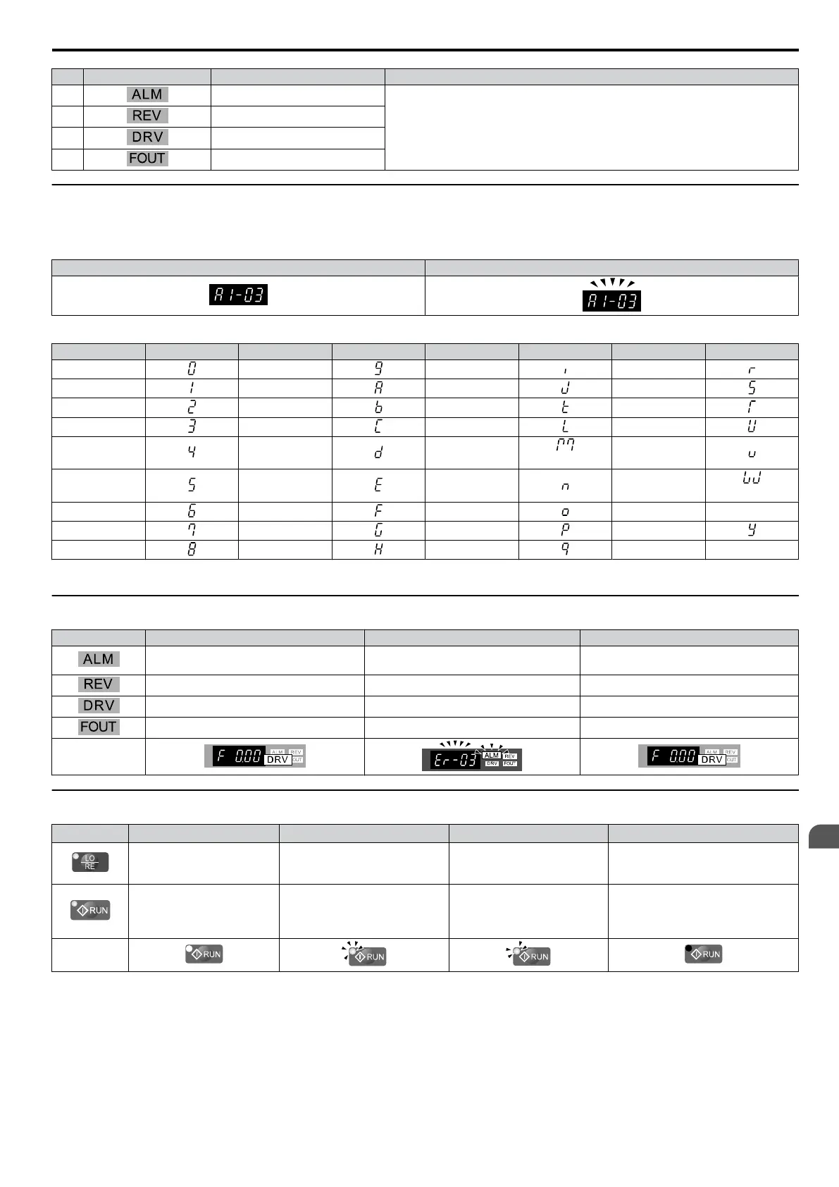
Digital Text Display
Text
appears on the LED Operator as shown below. This section explains the meaning of text as it appears on the display
screen.
Lit Flashing
Table 4.2 Digital Text Display
Text LED Text LED Text LED Text LED
0 9 I R
1 A J S
2 B K T
3 C L U
4 D M
<1>
V
5 E N W
<1>
6 F O X none
7 G P Y
8 H Q Z none
<1> Displayed in two digits.
u
LED Screen Displays
Display Lit Flashing Off
When the drive detects an alarm or error
• When an alarm occurs
•
oPE detected
Normal state (no fault or alarm)
Motor is rotating in reverse — Motor is rotating forward
Drive Mode — Programming Mode
Displays output frequency (Hz) — —
As illustrated in
this manual
u
LO/RE LED and RUN LED Indications
LED Lit Flashing
Flashing Quickly
<1>
Off
When run command is
selected from LED operator
(LOCAL)
— —
Run command is selected from
device other than LED operator
(REMOTE)
During run
• During deceleration to stop
•
When a run command is input
and frequency reference is 0
• During
deceleration at a fast-
stop.
• During stop by interlock
operation.
During stop
As shown
<1> Refer to Figure 4.1 for the difference between “flashing” and “flashing quickly”.
4.2 Using the Digital LED Operator
SIEP C710606 33A OYMC AC Drive – J1000 User Manual
55
4
Start-Up Programming
& Operation
 Loading...


