4.5 Powering Up the Drive
u
Powering Up the Drive and Operation Status Display
n
Powering Up the Drive
Review the following checklist before turning the power on.
Item to Check Description
Power supply voltage
Ensure the power supply voltage is correct:
200 V class: single-phase 200 to 240 Vac 50/60 Hz
200 V class: 3-phase 200 to 240 Vac 50/60 Hz
400 V class: 3-phase 380 to 480 Vac 50/60 Hz
Properly wire the power supply input terminals (R/L1, S/L2, T/L3).
(for single-phase 200 V class models, wire only R/L1 and S/L2)
Check for proper grounding of drive and motor.
Drive output terminals
and motor terminals
Properly wire drive output terminals U/T1, V/T2, and W/T3 with motor terminals U, V, and W.
Control circuit terminals Check control circuit terminal connections.
Drive control terminal status Open all control circuit terminals (off).
Status of the load
and connected machinery
Uncouple the motor from the load.
n
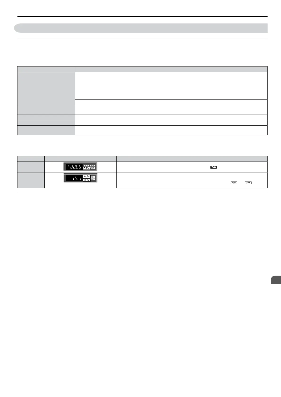
Status Display
When the power supply to the drive is turned on, the LED operator lights will appear as follows:
No. Name Description
Normal
Operation
The data display area displays the frequency reference. is lit.
Fault
Main circuit low voltage (ex)
Data displayed varies by the type of fault. Refer
to Fault Displays, Causes and Possible
Solutions on page 123 for more information and possible solution.
and are lit.
u
V/f Pattern Setting
Setting the V/f pattern according to the application. Refer to E: Motor Parameters on page 86 for details on setting the
V/f pattern.
n
Notes when Setting the V/f Pattern
Set the maximum output frequency to match the motor characteristics.
If the V/f pattern voltage is increased motor torque may also increase. However, if the V/f voltage is set too high these
problems may occur:
•
Excessive motor current.
• Motor overheat or vibration.
4.5 Powering Up the Drive
SIEP C710606 33A OYMC AC Drive – J1000 User Manual
63
4
Start-Up Programming
& Operation
 Loading...


