Flashing
ON ON
ON
ON ON
ON
1 s
Flashing
quickly
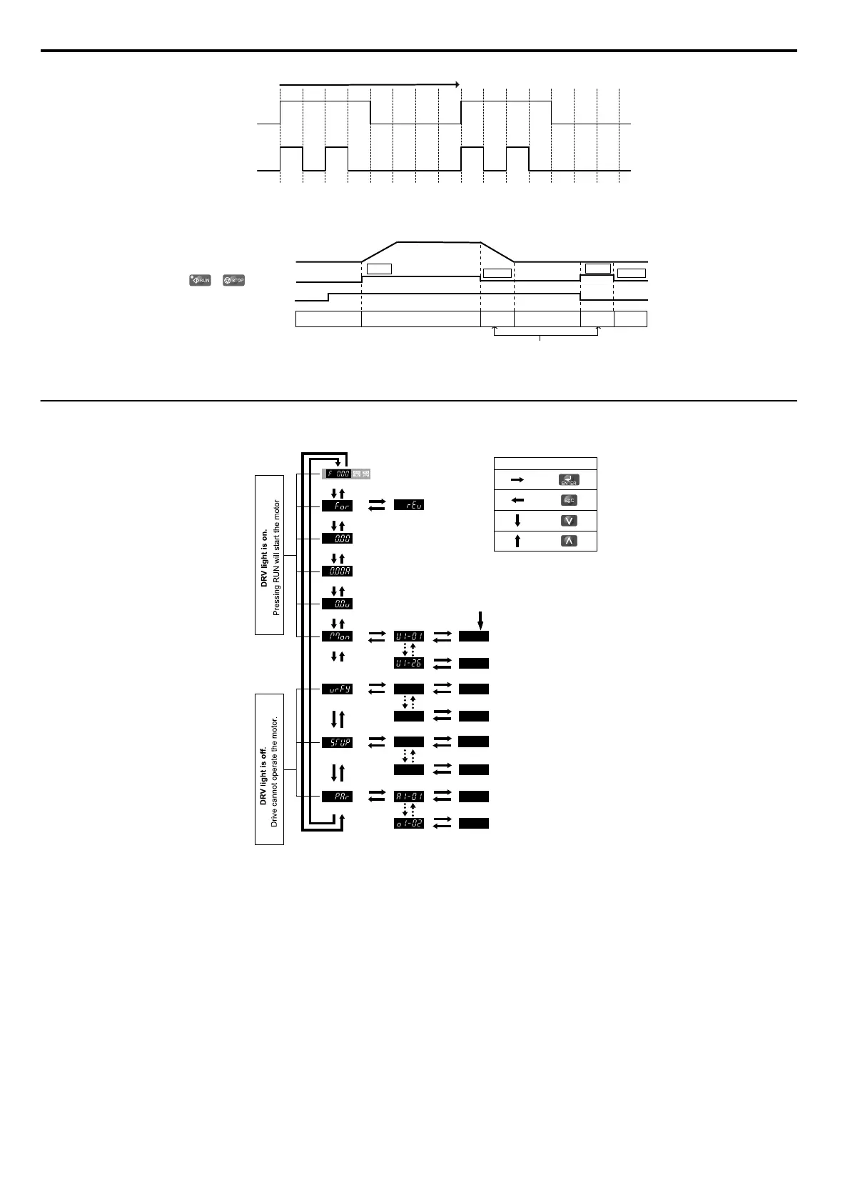
Figure 4.1 RUN LED Status and Meaning
/
Drive output frequency
during stop
Frequency setting
OFF
ON
Flashing
OFF
OFF
RUN LED
RUN
0 Hz
6 Hz
RUN
STOP
STOP
Figure 4.2 RUN LED and Drive Operation
u
Menu Structure for Digital LED Operator
XXXX
XX
XX
XX
XX
XX
XX
XX
XX
XX
XX
XX
XX
XX
XX
:
:
:
:
Turn the power on
Forward Selection
Reverse Selection
Output Frequency
Output Current
Output Voltage
Monitor Display
Note: “XX” characters are shown in this manual.
The drive will display the actual setting values.
<1>
Verify Menu
Set Up Mode
Parameter Setting Mode
Description of Key Operations
PROGRAMMING MODE
DRIVE MODE
Figure 4.3 Digital LED Operator Screen Structure
<1> Reverse can only be selected when LOCAL is set.
4.2 Using the Digital LED Operator
56
SIEP C710606 33A OYMC AC Drive – J1000 User Manual
 Loading...


